

-
Systems
- Choosing the Best Operating System for Servers: Corporate vs. Personal Use
- How to Activate Key on Windows
- How to add user account
- How to change date and time on windows 11
- How to use Snipping Tool to capture screenshots
- How to Recover Deleted Data
- How to Create and Use Disk Partitions on Windows and macOS
- How to use Terminal in macOS
- How to Repair System Files in Windows 11
- How to Install Optional Updates in Windows 11
- How to Optimize Your PC for Gaming
- How to Reset a Lost Admin Password on Mac OS X
- How to Fix It When an iPhone Is Stuck in SOS Mode
- How to enable Virtualization Technology on Lenovo PC computers
- How to Recover Your Data
- How to Connect AirPods to Kindle Fire
- How to Manage Scope Creep in Agile Through Backlog Grooming
- 7 Phases of Software Development Life Cycle
- How to Stop Windows 11 From Auto-Installing Device Drivers
- How to Disable Location Tracking on Windows 11
- How to Enable ADB on an Amazon Fire Tablet
- How to Clear Windows 11 Update Cache
- How to Enable XMP Memory Speed
- How to Install PIP on Windows
- How to Enable Hyper-V in Windows 11
- How to Show Hidden Files on Windows 11
- How to run Disk Defragment in Windows 11
- How to Backup Windows 11 Files to External Drive using File History
- How to enable screen saver on Windows 11
- How to change DNS server settings using Control Panel in Windows 11
- How to change monitor refresh rate on Windows 11
- How to Allow an App through Windows Firewall on Windows 11
- How to Reset Network Settings on Windows 11
- How to enable Resize BAR in BIOS setup
- How to Log in to Windows 11 With Facial Recognition
- How to build a computer in 30 minutes with EasyPCbuilder! - Gaming PC
- How to check your PC spec
- How to Check File integrity and Repair windows system flies.
- How to Partition A Hard Drive in Windows 11/10
- How to solving the problem "The User Profile Service failed the sign-in.User profile cannot be loaded." in Windows 10 operating system.
- Start your PC in safe mode in Windows
- How to Find your IP address in Windows
- System Testing: Explained
- Operating System: Functions
- Process Control Block in Operating System
- System Software vs Application Software: Differences
- How to turn on/off Remote Desktop on Windows 10
- How to unlock screen lock in registry on windows 10
- How to delete a language on windows 10
- How to delete a desired language in the Registry on Windows 10
- How to fix the Numlock key every time you power on Windows 10
- How to share folder to other PCs on the same network.
- How to fix The User Profile Service failed the sign-in User profile cannot be loaded.
- 4 Practical Methods to Disable Remote Desktop on Windows.
- How to Service Your Own Computer: 7 Easy Things Computer Repair Places Do
- How to Turn a Raspberry Pi into a Cheap Plex Player with RasPlex
- How to Overclock Your Raspberry Pi (Without Voiding Your Warranty)
- Reduced instruction set computing (RISC)
- Complex instruction set computing (SISC)
- Could not load file or assembly MOM.Implementation or its dependencies.
- How to overclock your CPU
- How to Create a System Image in Windows 7, 8, or 10
- Show Remaining Articles (47) Collapse Articles
-
- How to Disable the PIN in Windows 10?
- How to Install USB 3.0 Drivers on Windows 11
- How to Control the CPU Fan With First-Party Software on Windows 11
- How to Map a Network Drive on a Mac
- How to Fix Load Content Error in iOS 15
- Choosing the Best Operating System for Servers: Corporate vs. Personal Use
- How to Activate Key on Windows
- How to add user account
- How to change date and time on windows 11
- How to use Snipping Tool to capture screenshots
- How to stop BitLocker stuck on decrypting or encrypting
- How to backup data using Backup and Restore (Windows 7)
- How to perform Disk Cleanup in Windows OS
- How to Create and Use Disk Partitions on Windows and macOS
- How to use Terminal in macOS
- How to run an Ubuntu Desktop virtual machine using VirtualBox 7
- How to Take a Screenshot Using Built-in Tools
- How to Repair System Files in Windows 11
- How to Install Optional Updates in Windows 11
- How to block websites on Windows
- How to Optimize Your PC for Gaming
- How to Fix Mac Display Issues
- Fix the problem 'Your Windows License Will Expire Soon' in Windows 10
- How to Browse the Web in Your Linux Terminal With Lynx
- How to Fix Computer with No Sound on Windows 11
- How to Encrypt a Drive on Linux With VeraCrypt
- How to Delete a Username Credential Auto‐Complete Entry from Microsoft Edge on Windows 10
- How to Change MAC Address on Ubuntu
- How to recover a Dell Ubuntu Image on your Dell Computer
- How to Reset or Clear the DELL BIOS Password
- How to update Android Auto
- How to Sync iMessage to Mac
- How to Mute an iPad
- How to Pair and Connect AirPods to a Windows 11 PC
- How to Change the Administrator Account in Windows 11
- How to Turn Off Windows' Recall to Protect Your Privacy
- How to Remap a Keyboard on a Mac
- How to Mirror an iPhone to Fire Stick
- How to Change the Font in Windows 11
- How to Set Custom Low Battery Alerts on Windows 11
- How to See Which Programs Are Accessing Your Camera or Mic on Windows 11
- How to Change the Windows 11 Lock Screen Timeout
- How to Install Windows EXE Files on Mac With WineBottler
- How to Create a Black and White Printing Preset in MacOS
- How to Get New Message Alerts in Thunderbird for Windows
- How to Change the Default Location for Screenshots on macOS
- How to Turn on AirPlay Screen Mirroring on Your Mac
- How to Reassign Keys on a Mac Keyboard
- How to Force Quit in macOS With a Keyboard Shortcut
- How to Set an SD Card as the Default Storage Device on Android
- How to set Google Drive to Automatically Sync New Windows 11 Files
- How to Create an iCloud Email On Mac PC
- How to Fix When Windows 11 Is Stuck in Airplane Mode
- How to Fix Your Android Screen Not Rotating
- How to Share Wi-Fi Password From Phone to Mac
- How to Fix Gmail Not Syncing on Android
- How to Get Deleted Numbers Back on a Samsung Phone
- How to Resolve the Persistent "Google Keeps Stopping" Issue on Android
- How to Find Large Files on Windows 10
- What Is Reserved Storage in Windows 11?
- How to Identify a Windows on ARM PC
- How to Hide the Bar at the Bottom of iPhone Screen
- What is Windows PE and How to Use It
- How to Share Files Over Bluetooth on Windows 11
- How to Disable Paging File to Extend Your SSD’s Lifespan on Windows 11
- How to Use AirPlay on iPad
- How to Use Windows 11 as a Bluetooth Audio Receiver
- How to Enable ADB on an Amazon Fire Tablet
- How to Stop Windows 11 From Auto-Installing Device Drivers
- How to Disable Location Tracking on Windows 11
- How to Create a Shutdown Timer in Windows 10
- How to Create a Folder on a Mac
- How to Enable XMP Memory Speed
- How to Install PIP on Windows
- How to Enable Hyper-V in Windows 11
- How to Show Hidden Files on Windows 11
- How to Turn Off Mouse Acceleration in Windows 11
- How to install keyboard languages in Windows 11
- How to run Disk Defragment in Windows 11
- How to Backup Windows 11 Files to External Drive using File History
- How to enable screen saver on Windows 11
- How to change shortcut keys for switching input method in Windows 11
- How to change DNS server settings using Control Panel in Windows 11
- How to install and Configuring XAMPP on Windows 11
- How to change monitor refresh rate on Windows 11
- How to Allow an App through Windows Firewall on Windows 11
- How to turn on Notification History on Android Phone
- How to clear the cache on Android apps
- How to Set an Alarm on MacOS Using Reminders
- How to View All Available System Restore Points in Windows 10
- How to Set up Parental Controls in Windows 10
- How to delete a Windows Restore Point
- How to Enable Developer Options on Android Phone
- How to Disable Microsoft Touchpad in Windows 11
- How to Change Device Wake Permissions on Windows 11
- How to Save File From email in iOS
- How to Reset Network Settings on a Mac
- How to disable Device encryption in Windows 11
- How to use Focus Assist to Control Notifications in Windows 10
- How to Use Disk Quotas to Limit User Storage on Windows 11
- How to Fix Poor Quality Fonts or Text on Windows
- How to set static IP for Windows 10
- How to Log in to Windows 11 With Facial Recognition
- How to Change Login Picture in MacOS
- How to disable IPv6 on Windows 10
- How to Change App Store Country or Region
- How to Bypass internet requirement during Windows 11 Setup
- How to Calibrate Mac OS Monitor
- How to Add a Printer to a Mac via WPS
- What is Cloud Server?
- Windows shortcut
- How to fix fast-draining mobile phone batteries for all models
- Android and IOS
- How to Optimize Windows 10 Performance by tweaking Visual Effects
- Start your PC in safe mode in Windows
- How to Reset Windows 10 Using Command Prompt
- How to Find your IP address in Windows
- Operating System: Functions
- Process Control Block in Operating System
- How to fix windows 11 unable to update error 0xC1900101
- How to turn on/off Remote Desktop on Windows 10
- How to delete a desired language in the Registry on Windows 10
- How to fix the Numlock key every time you power on Windows 10
- How to Change the Measurement Unit in Microsoft PowerPoint
- How to change Mouse pointer looks
- How to Create a Custom Power Plan
- Show Remaining Articles (111) Collapse Articles
-
- What Are Domains and Forests?
- Configure DHCP Using Policy-based Assignment
- Install Hyper-V and create a virtual machine
- Install Exchange Server 2013 in Windows Server 2012
- 16 Windows Terminal commands every user should know
- Restoring the DHCP Database from Backup
- Backing Up the DHCP Database
- Back up a Group Policy object using GPMC
- Reset the Domain Admin password in Windows Server 2012 R2
- How to Add Image To Windows Deployment Services
- How to Configure Windows Deployment Services
- How to Install WDS on Windows server 2012 R2
- Windows Server 2012 R2 Remote Desktop Services (RDS) Installation And Publish RemoteApp
- Windows Server 2012 R2 Creating Active Directory Objects And Linking a Group Policy Object
- Group Policy - use regional settings to change date format
- How to disable USB devices using Group Policy
- How to Hide Drives using Group Policy in Windows Server 2012 R2
- How to force proxy settings via Group Policy on Windows Server 2012
- Enforce Windows Server 2012 Client Computers to Have the Desktop Wallpaper That I Specify
- How to Map Network Drives on Windows Clients via Group Policy
- Disable Strong Password Enforcement and Password Aging
- Creating & Configure GPO in Windows Server 2012 R2
- Installing and Configuring target iSCSI server on Windows Server 2012
- Configuring a Syslog Agent in Windows Server 2012
- What Are Domains and Forests?
- Install Exchange Server 2013 in Windows Server 2012
- Show Remaining Articles (11) Collapse Articles
-
- Mac - Entering a User Code for a Ricoh Printer
- How to Map a Network Drive on a Mac
- Choosing the Best Operating System for Servers: Corporate vs. Personal Use
- How to Create and Use Disk Partitions on Windows and macOS
- How to use Terminal in macOS
- How to run an Ubuntu Desktop virtual machine using VirtualBox 7
- How to Take a Screenshot Using Built-in Tools
- How to Fix Mac Display Issues
- How to extract text from images on a Mac
- How to Reset a Lost Admin Password on Mac OS X
- How to Change MAC Address on Ubuntu
- How to Sync iMessage to Mac
- How to Remap a Keyboard on a Mac
- How to Install Windows EXE Files on Mac With WineBottler
- How to Create a Black and White Printing Preset in MacOS
- How to Change the Default Location for Screenshots on macOS
- How to Turn on AirPlay Screen Mirroring on Your Mac
- How to Reassign Keys on a Mac Keyboard
- How to Force Quit in macOS With a Keyboard Shortcut
- How to Create an iCloud Email On Mac PC
- How to Share Wi-Fi Password From Phone to Mac
- How to Create a Folder on a Mac
- How to Set an Alarm on MacOS Using Reminders
- How to create an App-Specific Password for your Apple ID account
- How to Reset Network Settings on a Mac
- How to Change Login Picture in MacOS
- How to Set Up Network File Sharing on macOS, Without Sharing Your Username and Password
- How to Write to NTFS Drives in OS X Mavericks
- How to Calibrate Mac OS Monitor
- How to Add a Printer to a Mac via WPS
- 7 Fixes for MacBook Keeps Restarting
- How to Play Hidden Games on Your Mac
- How to screen share with iOS and macOS to help friends and family with new devices
- How to Install macOS High Sierra on VMware on Windows.
- Mac Basics
- How to Map a Network Drive on a Mac
- How to Monitor and Control Your Mac Fans
- How to Upgrade Your Computer's Login Screen
- Create Hidden Administrative Accounts in OS X from the Terminal
- Sort Folders and Files on Mac Just Like Windows With a Single Setting Switch
- Move a PiP Video Player Window Anywhere on Mac
- Reset the System Management Controller (SMC) on your Mac
- How to Merge Multiple Finder Windows on macOS
- How to Rotate a Video On Your Mac
- How to Decrypt External Drives on Mac
- How to Where Default Desktop Pictures Are Located in Mac OS X
- How to Add Siri Results into Notification Center on Mac
- How to 4 Ways to Convert PDF to Word DOCX in Mac OS
- How to Download a File from a Server with SSH / SCP
- How to Batch Change File Extensions in Mac OS
- How to Remove Safari Extensions on Mac
- How to Hide MacOS Sierra Update Banner from the Mac App Store
- How to Add Siri Results into Notification Center on Mac
- How to Add Siri Results into Notification Center on Mac
- How to Change MacOS Sierra GUI System Font to Lucida Grande
- How to Capitalize Words and Add Periods Automatically in Mac OS
- How to Clean a MacBook Pro Keyboard the Easy Way with Keyboard Cleaner
- How to Manually Check for New eMail in Mail for Mac with a Keyboard Shortcut
- How to Summarize Lengthy Documents & Pages in Mac OS
- How to Trim Movies in Photos for Mac
- How to Save or Convert Word Doc to PDF on Mac
- How to Erase a Disk from Command Line in Mac OS X
- How to Disable the Focus Ring Animation in Mac OS X
- How to Disable Hot Corners in Mac OS X
- How to Open .pkg Files to View What Will Install on Mac with Suspicious Package
- How to Hide Siri Menu Icon in macOS
- How to Clean Install macOS Sierra
- How to Allow Apps from Anywhere in macOS Sierra Gatekeeper
- How to Resize a Photo on Mac
- How to find out the charge cycle count on an Apple Mac
- Zip files do not unzip Mac OSX
- How to Enable Accessibility on Mac OS X 10.11 El Capitan
- Finding your Mac's UUID
- How to eject a disk properly on OS X
- How to change your Mac's default Web browser and email app
- How to Turn Your Mac Into a Wi-Fi Hotspot
- Ethernet port not working in Mac OS X El Capitan
- How to add a signature automatically to every message in Mac
- How to Uninstall Most Mac Applications
- Uninstall Office 2011 for Mac
- How Do I Enable Skype for Business/Lync Logging?
- Getting Started With Lync for Mac
- How to Install Windows on a Mac With Boot Camp
- 20 Terminal shortcuts developers need to know
- How to Create Bootable USB From a Windows ISO for Mac
- How to Format an External Drive for Mac Compatibility
- Deleting Cache and Log Files Manually on the Mac.
- How to force an app to close on your Mac.
- How to Print a Test Page on Mac
- How to change a printer's name and location Mac OS.
- How to change your default printer Mac OS.
- How to set the date and time on your Mac
- How to review remaining space on your Mac hard drive
- How to check serial number OS X Mavericks or earlier.
- How to check serial number OS X Yosemite.
- How to check Mac OS version.
- How to set the resolution for a connected display Mac OS
- How to set the resolution for your primary display Mac OS
- How to use input sources to type in other languages on a Mac
- How to map a network drive in Mac OS X
- How to Set a Manual IP Address in Mac OS X
- How to ping test in Mac OS X
- How to reinstall OS X from recovery
- Introduction to the Mac OS X Command Line
- How to Install Windows on a Mac With Boot Camp
- How to Print Double Sided on Mac
- How to Trigger an Alert Dialog Pop-Up from Command Line in Mac OS
- How to Search in PDF on Mac with Preview
- How to Prepare for & Install macOS Sierra
- Fix Wi-Fi Problems in macOS Sierra
- How to Create a Bootable macOS Sierra Installer
- How to Downgrade macOS Sierra & Revert to El Capitan
- Show Remaining Articles (97) Collapse Articles
-
- Add Control Panel (Or Any Program) To Your Right-Click Menu With a Registry Tweak
- How To Fix STOP 0x00000005 Errors
- How To Fix STOP 0x0000007B Errors
- How To Fix Ssleay32.dll Not Found or Missing Errors
- How To Fix Sqlite3.dll Not Found or Missing Errors
- How To Fix Shell32.dll Not Found or Missing Errors
- How To Fix Oleaut32.dll Not Found or Missing Errors
- How to Fix Ole32.dll Not Found or Missing Errors
- How To Fix Msxml6.dll Errors
- How To Fix Msvcr70.dll Not Found or Missing Errors
- How To Fix Msvcp80.dll Not Found or Missing Errors
- How To Fix Msvcp71.dll Not Found or Missing Errors
- How to Fix Mfc90.dll Not Found or Missing Errors
- How to Fix Mfc42.dll Not Found or Missing Errors
- How To Fix Libxml2.dll Not Found or Missing Errors
- How to Fix Gdi32.dll Not Found or Missing Errors
- How to Fix Fm20.dll Not Found or Missing Errors
- How To Fix Comdlg32.dll Not Found or Missing Errors
- How To Fix a Blue Screen of Death
- How do I renew the IP address for my computer ?
- What Is A Trace Route (tracert)? How Do I Run One?
- Tricks: Change Your IP Address From the Command Prompt
- Create and format a new partition (volume)
- How to change, add, or remove a drive letter
- 16 Windows Terminal commands every user should know
- How to fix "The User Profile Service failed the logon. User profile cannot be loaded"
- How to List All of the Windows and Software Updates Applied to a Computer
- Quickly Turn ON/OFF Windows Firewall Using Command Line
- How to ping test in Windows 7 and Vista
- Configuring PHP Development Environment in Windows
- Show Remaining Articles (15) Collapse Articles
-
- What is Swappiness in Linux?
- How to Change MySQL User Root Password in Linux
- How to Edit Linux Hosts File?
- How to migrate CentOS 7 to Rocky Linux 9
- How to Reset MySQL Root Password in Windows
- How to Browse the Web in Your Linux Terminal With Lynx
- How to Encrypt a Drive on Linux With VeraCrypt
- How to troubleshoot Linux server memory issues
- Installing Ubuntu Desktop
- How to transfer PuTTY sessions from one PC to another
- How to get started with Linux
- Upstream connection to Nginx fails with error:connect() failed (111: Unknown error)
- How to Create a Live Ubuntu USB Drive With Persistent Storage
- Basic Linux Shell Commands
- How to Install CentOS 7 Step by Step with Screenshots.
- How to Install Software on Linux
- How to Create Bootable USB from a Linux ISO
- Samba4 as a Domain Controller
- How to Set Up Samba for Windows-Linux File Sharing
- Install Ubuntu 14.04.4 LTS
- Show Remaining Articles (5) Collapse Articles
-
- How to stop BitLocker stuck on decrypting or encrypting
- How to Create and Use Disk Partitions on Windows and macOS
- How to Fix Poor Quality Fonts or Text on Windows
- How to Changing BIOS mode from UEFI to Legacy
- How to Find Drivers for Devices Using a Hardware ID
- How To Fix A Corrupted Pen Drive Or SD Card Using CMD.
- How to Bypass Windows 10 / 8 / 7 Local Administrator Password.
- Windows shortcut
- How to Optimize Windows 10 Performance by tweaking Visual Effects
- Install Hyper-V and create a virtual machine
- How to turn off Windows Automatic Updates in Windows 8/8.1
- How to Map a Network Drive in Windows 10
- 10 Useful Windows Commands You Should Know
- How to Do a Clean Install of Windows Without Losing Your Files, Settings, and Tweaks
- How to Use Windows 8's New File History Backup (aka Time Machine for Windows)
- Add Control Panel (Or Any Program) To Your Right-Click Menu With a Registry Tweak
- How To Fix STOP 0x00000005 Errors
- How To Fix STOP 0x0000007B Errors
- How To Fix Ssleay32.dll Not Found or Missing Errors
- How To Fix Sqlite3.dll Not Found or Missing Errors
- How To Fix Shell32.dll Not Found or Missing Errors
- How To Fix Oleaut32.dll Not Found or Missing Errors
- How to Fix Ole32.dll Not Found or Missing Errors
- How To Fix Msxml6.dll Errors
- How To Fix Msvcr70.dll Not Found or Missing Errors
- How To Fix Msvcp80.dll Not Found or Missing Errors
- How To Fix Msvcp71.dll Not Found or Missing Errors
- How to Fix Mfc90.dll Not Found or Missing Errors
- How to Fix Mfc42.dll Not Found or Missing Errors
- How To Fix Libxml2.dll Not Found or Missing Errors
- How to Fix Gdi32.dll Not Found or Missing Errors
- How to Fix Fm20.dll Not Found or Missing Errors
- How To Fix Comdlg32.dll Not Found or Missing Errors
- How To Fix a Blue Screen of Death
- How to Disable Access to the Windows Registry
- How to Fix Windows Update When It Gets Stuck
- How to Batch Rename Multiple Files in Windows
- How to Fix Hard Drive Problems with Chkdsk in Windows 7, 8, and 10
- How to Use OneDrive as Your Default Save Location on Windows 8.1
- How to Find and Remove Duplicate Files on Windows
- What Are the FOUND.000 Folder and FILE0000.CHK File in Windows?
- How to Upgrade to a Larger Hard Drive Without Reinstalling Windows
- How to Migrate Your Windows Installation to a Solid-State Drive
- How to Hide Items from the Control Panel in Windows
- How Secure Boot Works on Windows 8 and 10, and What It Means for Linux
- How to Stop Aero Shake from Minimizing Your Windows
- How to Change the Default Control Panel View in Windows
- How to Disable the Lock Workstation Functionality (Window+L) in Windows
- How to Remove Local User Accounts From the Login Screen in Windows
- How to Fix Hard Drive Problems with Chkdsk in Windows 7, 8, and 10
- How to Delete a User Account in Windows 7, 8, or 10
- How to Disable Driver Signature Verification on 64-Bit Windows 8 or 10 (So That You Can Install Unsigned Drivers)
- How to Create a Guest Account in Windows 10
- How to Recover Software Product Keys From Any Computer, Even a Broken One
- How to Change the Color of Window 7 and Windows 8 Folder
- Turn your Laptop into WIFI hotspot in One Click Without Software
- Most Amazing Notepad Tricks that Works in Your PC
- Monitor Windows PC Internet Data Usage in Real-Time
- Shareit: Transfer Data between two or more laptop without WiFi Connection
- Instructions for Sharing Data Between Two Computers/Laptop Using Minishare Software
- Change Window 7 and Window 10 Password Without Knowing old Password from Command Prompt
- How to set up desktop background image rotation in Windows 8
- How to access Safe mode in Windows 8
- How to adjust your Laptops screen brightness in Windows 8/8.1
- Bypass Windows 8 and 8.1 login screen
- 20 Windows 8 and 8.1 shortcuts
- Schedule Windows to shutdown or restart after a time limit
- How to install Kaspersky Security Center 10 on Microsoft Windows Server Core Mode
- How to make a full backup of a Windows 10 or Windows 8.1 PC
- Change your display language in Windows 8
- How to change keyboard layout in Windows
- How to change the display language in Windows
- How to Create a System Image in Windows 7, 8, or 10
- How do I renew the IP address for my computer ?
- Manually remove a Click-to-Run installation of Office
- Getting Started With Skype for Business for Windows
- What Is A Trace Route (tracert)? How Do I Run One?
- Tricks: Change Your IP Address From the Command Prompt
- How to restore a Windows 8 laptop or PC to factory default settings
- Reset Windows Activation/Remove license key
- Create and format a new partition (volume)
- How to change, add, or remove a drive letter
- 16 Windows Terminal commands every user should know
- How To Enable Windows Defender On Windows 8/Windows 8.1
- How to remove apps and programs Windows.
- How to disable Windows 8.1 Startup Programs.
- Change the Remote Desktop Connection port to your Windows Server
- Getting To Safe Mode From Within Windows 8 or 10
- Disable Office updates on Windows 8.1 or Windows 7
- How to List All of the Windows and Software Updates Applied to a Computer
- Quickly Turn ON/OFF Windows Firewall Using Command Line
- Remove a saved wireless network
- Disable Built-in Administrator Account
- Enable Built-in Administrator Account in Windows
- Enable Hyper-V on Windows 8.1
- How to perform ping test in Windows 8
- How to change your screen resolution
- How To Make UEFI Bootable USB Flash Drive to Install Windows 8
- Show Remaining Articles (83) Collapse Articles
-
- OneDrive SharePoint Not Syncing
- How to choose a laptop in 2024, what to look for?
- How to Disable the PIN in Windows 10?
- Choosing the Best Operating System for Servers: Corporate vs. Personal Use
- Delete a SharePoint site or subsite
- How to stop BitLocker stuck on decrypting or encrypting
- How to backup data using Backup and Restore (Windows 7)
- How to perform Disk Cleanup in Windows OS
- How to Create and Use Disk Partitions on Windows and macOS
- How to Check Number of Cores and Threads in My Processor
- How to Uninstall or remove apps and programs in Windows
- How To Take Screenshot On Windows
- How to Remove malware from your Windows PC
- How To Enable All Cores in Windows
- How to Create a Desktop Shortcut on Windows
- How to Access the BIOS on Any PC
- How to fix 100% disk usage in Windows 10
- How to block websites on Windows
- How to check if a port is open on a Windows machine?
- Fix the problem 'Your Windows License Will Expire Soon' in Windows 10
- How to Fix ‘No Battery Is Detected’ on Your Laptop
- How to Delete a Username Credential Auto‐Complete Entry from Microsoft Edge on Windows 10
- How to Identify AI-Enabled Windows Computers
- How to optimize disk usage when the system is slow - Windows 10 and Windows 11
- How to Upgrading from Windows 7 to Windows 10
- How to Disable Secure Boot on Dell laptop?
- How to Factory Reset Your Windows PC
- How to Reset BIOS Settings on Windows PCs
- How to fix Windows 10 Taskbar Not Working
- How to Turn Off Windows' Recall to Protect Your Privacy
- How to Get New Message Alerts in Thunderbird for Windows
- How to Find Large Files on Windows 10
- How to Create a Shutdown Timer in Windows 10
- How to Install PIP on Windows
- How to View All Available System Restore Points in Windows 10
- How to Set up Parental Controls in Windows 10
- How to delete a Windows Restore Point
- How to use Focus Assist to Control Notifications in Windows 10
- How to Fix Poor Quality Fonts or Text on Windows
- How to set static IP for Windows 10
- How to change the fonts in Google Chrome for Windows 10
- How to disable IPv6 on Windows 10
- How to Changing BIOS mode from UEFI to Legacy
- How to Find Drivers for Devices Using a Hardware ID
- How To Fix A Corrupted Pen Drive Or SD Card Using CMD.
- How to Bypass Windows 10 / 8 / 7 Local Administrator Password.
- How to Speed Up Windows 10
- Windows shortcut
- How to Set Up and Use Remote Desktop for Windows 10
- 3 Ways to Change User Account Name in Windows 10
- How to Optimize Windows 10 Performance by tweaking Visual Effects
- How to Check the Application Event Log for Errors
- How to Create a Shortcut to Windows Update in Window
- Install Hyper-V and create a virtual machine
- Connecting Bluetooth headphones on Windows 10
- How to change account (Switch your Microsoft account to a local account.)
- How to change password settings and change passwords
- How to adjust the Refresh Rate of the screen in Windows 10
- How to reset and clean your computer Make it smooth like new. without using a Flash Drive
- How to Check File integrity and Repair windows system flies.
- How to Partition A Hard Drive in Windows 11/10
- How to automatically delete junk files to free up space on Windows 10
- How to turn off Windows Defender permanently
- How to Turn Off Automatic Updates on Windows 10/11
- How to check if Windows 10 is genuine
- How to solving the problem "The User Profile Service failed the sign-in.User profile cannot be loaded." in Windows 10 operating system.
- How to Reset Windows 10 Using Command Prompt
- How to Add Microsoft Store App to Desktop in Windows 11/10
- How to encrypt a file
- How to create a recovery drive
- Simple Ways to Erase and Format a USB Flash Drive.
- Wi-Fi Network Not Showing Up on Computer.
- When windows are unable to boot to the desktop.
- Windows 10 Tip: Get started with the emoji keyboard shortcut.
- How to set the time and date in Windows 10 to solve the problem of the time and date being out of sync.
- How to Fix Mouse Lag on Windows 10
- How to change the language of Windows 10 from English to Thai
- Turn off Driver Auto Update in Windows 10
- How to turn on/off Remote Desktop on Windows 10
- How to unlock screen lock in registry on windows 10
- How to delete a language on windows 10
- How to delete a desired language in the Registry on Windows 10
- How to fix the Numlock key every time you power on Windows 10
- How to Fix Remote Desktop Not Allowing Copy-Paste.
- How to share folder to other PCs on the same network.
- How to fix The User Profile Service failed the sign-in User profile cannot be loaded.
- How to change desktop background image in Windows 10
- How to change keyboard language shortcut in Windows 10
- 4 Practical Methods to Disable Remote Desktop on Windows.
- How to Turn Autocorrect on or Off in Windows 10
- How to turn off all notification window 10
- How to Defragment your Windows 10
- How to change Your default web browser
- How To Change Your IP Address Window 10
- How to Check If Windows 10 Is Activated
- How to turn Off Windows Update in Windows 10
- How to Back Up Files with File History in Windows 10
- How to Map a Network Drive in Windows 10
- How to Use the Cortana Voice Assistant in Windows 10
- 4 ways to set auto shutdown in Windows 10
- 10 Useful Windows Commands You Should Know
- How to Install macOS High Sierra on VMware on Windows.
- How to Do a Clean Install of Windows Without Losing Your Files, Settings, and Tweaks
- How to Upgrade Your Computer's Login Screen
- Add Control Panel (Or Any Program) To Your Right-Click Menu With a Registry Tweak
- How to Move the Clock to Right-Most Corner on the Taskbar in Windows 10
- EdgeDeflector Forces Cortana to Use Your Default Web Browser
- Keep the Windows 10 Taskbar Visible While Using the On-Screen Keyboard
- How To Fix STOP 0x00000005 Errors
- How To Fix STOP 0x0000007B Errors
- How To Fix Ssleay32.dll Not Found or Missing Errors
- How To Fix Sqlite3.dll Not Found or Missing Errors
- How To Fix Shell32.dll Not Found or Missing Errors
- How To Fix Oleaut32.dll Not Found or Missing Errors
- How to Fix Ole32.dll Not Found or Missing Errors
- How To Fix Msxml6.dll Errors
- How To Fix Msvcr70.dll Not Found or Missing Errors
- How To Fix Msvcp80.dll Not Found or Missing Errors
- How To Fix Msvcp71.dll Not Found or Missing Errors
- How to Fix Mfc90.dll Not Found or Missing Errors
- How to Fix Mfc42.dll Not Found or Missing Errors
- How To Fix Libxml2.dll Not Found or Missing Errors
- How to Fix Gdi32.dll Not Found or Missing Errors
- How to Fix Fm20.dll Not Found or Missing Errors
- How To Fix a Blue Screen of Death
- How to Disable Access to the Windows Registry
- How to Fix Windows Update When It Gets Stuck
- How to Batch Rename Multiple Files in Windows
- How to Fix Hard Drive Problems with Chkdsk in Windows 7, 8, and 10
- How to Use Sticky Notes on Windows 10
- How to Find and Remove Duplicate Files on Windows
- What Are the FOUND.000 Folder and FILE0000.CHK File in Windows?
- How to Upgrade to a Larger Hard Drive Without Reinstalling Windows
- How to Stop Skype from Running in the Background on Windows 10
- How to Stop Skype from Running in the Background on Windows 10
- How to Migrate Your Windows Installation to a Solid-State Drive
- All the Ways You Can Still Get Windows 10 for Free
- How to Hide Items from the Control Panel in Windows
- How Secure Boot Works on Windows 8 and 10, and What It Means for Linux
- How to Stop Aero Shake from Minimizing Your Windows
- How to Change the Default Quiet Hours in Windows 10
- How to Change the Default Control Panel View in Windows
- How to Disable the Lock Workstation Functionality (Window+L) in Windows
- How to Remove Local User Accounts From the Login Screen in Windows
- How to Fix Hard Drive Problems with Chkdsk in Windows 7, 8, and 10
- How to Delete a User Account in Windows 7, 8, or 10
- How to Disable Driver Signature Verification on 64-Bit Windows 8 or 10 (So That You Can Install Unsigned Drivers)
- How to Create a Guest Account in Windows 10
- How to Recover Software Product Keys From Any Computer, Even a Broken One
- Turn your Laptop into WIFI hotspot in One Click Without Software
- Most Amazing Notepad Tricks that Works in Your PC
- Monitor Windows PC Internet Data Usage in Real-Time
- Access your Shared PC Drives and Folders from Android Mobile
- Shareit: Transfer Data between two or more laptop without WiFi Connection
- Instructions for Sharing Data Between Two Computers/Laptop Using Minishare Software
- How To Encrypt and Password Protect your USB PenDrive in Window 10
- Increase the Size your Computer Hard Disk up to 2TB in Window 10
- Change Window 7 and Window 10 Password Without Knowing old Password from Command Prompt
- How to Install Hyper-V on Windows 10
- HOW TO CONTROL YOUR PRIVACY IN CHROMEBOOKS VS. WINDOWS 10
- Schedule Windows to shutdown or restart after a time limit
- Make Windows 10 notify you before downloading or installing Windows Updates
- How to to Turn Off Windows Update in Windows 10
- How to generate a Battery Report in Windows 10.
- How to use Storage Spaces in Windows 10
- How to disable Action Center in Windows 10
- 16 Essential keyboard shortcuts everyone should know using Continuum for phones
- Use Windows Defender Offline to remove tough viruses from your Windows 10 PC
- How to change the system language across your whole Windows 10 PC
- How to re-activate Windows 10 after a hardware change
- How to disable or uninstall OneDrive on Windows 10 PC
- How to fix taskbar search not working in Windows 10
- How to use Bing images within Office and Edge on Windows 10 PC.
- How to install Kaspersky Security Center 10 on Microsoft Windows Server Core Mode
- How to control your Windows 10 PC or phone with another computer with the Connect app
- How to properly remove the Windows.old folder on Windows 10
- How to create a System Restore Point in Windows 10 with a simple double-click
- How to make a full backup of a Windows 10 or Windows 8.1 PC
- Is your Windows 10 PC slowing you down, and the SFC utility is unable to fix the problem? Then use DISM to repair the Windows image to enable SFC to do its job.
- How to revert to previous operating systems from Windows 10
- How to disable Windows 10 Upgrade
- How to reset password on Windows 10
- How to change keyboard layout in Windows
- How to change the display language in Windows
- Create a local user account in Windows 10
- How to Change / Set a Password in Windows 10
- How to Create a System Image in Windows 7, 8, or 10
- How do I renew the IP address for my computer ?
- Manually remove a Click-to-Run installation of Office
- Getting Started With Skype for Business for Windows
- What Is A Trace Route (tracert)? How Do I Run One?
- Tricks: Change Your IP Address From the Command Prompt
- Reset Windows Activation/Remove license key
- Create and format a new partition (volume)
- How to change, add, or remove a drive letter
- 16 Windows Terminal commands every user should know
- How to set the Default Printer on Windows 10.
- Change the Remote Desktop Connection port to your Windows Server
- Getting To Safe Mode From Within Windows 8 or 10
- Disable Office 2016/2013 updates on Windows 10
- How to List All of the Windows and Software Updates Applied to a Computer
- Quickly Turn ON/OFF Windows Firewall Using Command Line
- Remove a saved wireless network
- Disable Built-in Administrator Account
- Enable Built-in Administrator Account in Windows
- How to perform ping test in Windows 10
- Show Remaining Articles (191) Collapse Articles
-
- How to stop BitLocker stuck on decrypting or encrypting
- How to Create and Use Disk Partitions on Windows and macOS
- How to Upgrading from Windows 7 to Windows 10
- How to Fix Poor Quality Fonts or Text on Windows
- How to Bypass Windows 10 / 8 / 7 Local Administrator Password.
- Windows shortcut
- How to Setting Password Protected Print Jobs
- How to Run Disk Cleanup on a Windows 7 Computer
- How To Disable Updates in Windows 7
- 10 Useful Windows Commands You Should Know
- Add Control Panel (Or Any Program) To Your Right-Click Menu With a Registry Tweak
- How To Fix STOP 0x00000005 Errors
- How To Fix STOP 0x0000007B Errors
- How To Fix Ssleay32.dll Not Found or Missing Errors
- How To Fix Sqlite3.dll Not Found or Missing Errors
- How To Fix Shell32.dll Not Found or Missing Errors
- How To Fix Oleaut32.dll Not Found or Missing Errors
- How to Fix Ole32.dll Not Found or Missing Errors
- How To Fix Msxml6.dll Errors
- How To Fix Msvcr70.dll Not Found or Missing Errors
- How To Fix Msvcp80.dll Not Found or Missing Errors
- How To Fix Msvcp71.dll Not Found or Missing Errors
- How to Fix Mfc90.dll Not Found or Missing Errors
- How to Fix Mfc42.dll Not Found or Missing Errors
- How To Fix Libxml2.dll Not Found or Missing Errors
- How to Fix Gdi32.dll Not Found or Missing Errors
- How to Fix Fm20.dll Not Found or Missing Errors
- How To Fix Comdlg32.dll Not Found or Missing Errors
- How To Fix a Blue Screen of Death
- How to Disable Access to the Windows Registry
- How to Fix Windows Update When It Gets Stuck
- How to Batch Rename Multiple Files in Windows
- How to Fix Hard Drive Problems with Chkdsk in Windows 7, 8, and 10
- How to Find and Remove Duplicate Files on Windows
- What Are the FOUND.000 Folder and FILE0000.CHK File in Windows?
- How to Upgrade to a Larger Hard Drive Without Reinstalling Windows
- How to Migrate Your Windows Installation to a Solid-State Drive
- How to Hide Items from the Control Panel in Windows
- How to Change the Default Control Panel View in Windows
- How to Disable the Lock Workstation Functionality (Window+L) in Windows
- How to Remove Local User Accounts From the Login Screen in Windows
- How to Fix Hard Drive Problems with Chkdsk in Windows 7, 8, and 10
- How to Delete a User Account in Windows 7, 8, or 10
- INCREASE BATTERY LIFE OF LAPTOP EASILY
- How to Change the Color of Window 7 and Windows 8 Folder
- Turn your Laptop into WIFI hotspot in One Click Without Software
- Most Amazing Notepad Tricks that Works in Your PC
- Change Window 7 and Window 10 Password Without Knowing old Password from Command Prompt
- Windows 7 Guide to using Microsoft Security Essentials
- Microsoft Security Essential Install, Windows 7
- How to Create a System Image in Windows 7, 8, or 10
- How do I renew the IP address for my computer ?
- Manually remove a Click-to-Run installation of Office
- How Do I Enable Skype for Business/Lync Logging?
- What Is A Trace Route (tracert)? How Do I Run One?
- Tricks: Change Your IP Address From the Command Prompt
- Reset Windows Activation/Remove license key
- Create and format a new partition (volume)
- How to change, add, or remove a drive letter
- 16 Windows Terminal commands every user should know
- How to Create Bootable USB From a Windows ISO for Mac
- How to Create Bootable USB from an IMG File
- How to Create Bootable USB from a Windows ISO
- How to Repair a Windows 7 System with an Installation Disc
- How to printing a Test Page in Windows 7.
- Connect your computer to a domain on Windows 7
- How to fix "The User Profile Service failed the logon. User profile cannot be loaded"
- Disable Office updates on Windows 8.1 or Windows 7
- How to List All of the Windows and Software Updates Applied to a Computer
- Installing SP1 using an installation DVD
- Uninstalling SP1 using the Command Prompt
- Uninstalling SP1 using Programs and Features
- Quickly Turn ON/OFF Windows Firewall Using Command Line
- Turning Off BitLocker Drive Encryption (Windows 7)
- Show Remaining Articles (59) Collapse Articles
-
- OneDrive SharePoint Not Syncing
- How to choose a laptop in 2024, what to look for?
- How to Install USB 3.0 Drivers on Windows 11
- How to Control the CPU Fan With First-Party Software on Windows 11
- How to use Copilot in Microsoft Dynamics 365 for max productivity
- Back up your BitLocker recovery key
- How to Activate Key on Windows
- How to add user account
- How to change date and time on windows 11
- How to use Snipping Tool to capture screenshots
- Delete a SharePoint site or subsite
- How to stop BitLocker stuck on decrypting or encrypting
- How to Install Fonts on Windows 11: Three Easy Methods
- How to backup data using Backup and Restore (Windows 7)
- How to perform Disk Cleanup in Windows OS
- How to Create and Use Disk Partitions on Windows and macOS
- How to Take a Screenshot Using Built-in Tools
- How to Repair System Files in Windows 11
- How to Install Optional Updates in Windows 11
- How to Fix Missing Wi-Fi on Windows 11
- Hide recent folders/files from Quick Access in Windows 11
- How to Check Number of Cores and Threads in My Processor
- How to Uninstall or remove apps and programs in Windows
- How To Take Screenshot On Windows
- How to Remove malware from your Windows PC
- How To Enable All Cores in Windows
- How to Create a Desktop Shortcut on Windows
- How to Access the BIOS on Any PC
- How to fix 100% disk usage in Windows 10
- How to Change Mouse Cursor Size and Style on Windows 11
- How to block websites on Windows
- How to Force Close Apps in Windows 11
- How to scan QR Code on Windows 11
- How to change screen orientation in Windows 11
- How to Set a User Account in Windows 11 as Administrator
- How to Uninstall Windows 11 Updates
- How to Fix Computer with No Sound on Windows 11
- How to Fix ‘No Battery Is Detected’ on Your Laptop
- How to Create a Hotspot in Windows 11
- How to Identify AI-Enabled Windows Computers
- How to optimize disk usage when the system is slow - Windows 10 and Windows 11
- How to Disable Secure Boot on Dell laptop?
- How to Get Your Product Key in Command Prompt
- How to Factory Reset Your Windows PC
- How to Reset BIOS Settings on Windows PCs
- How to Pair and Connect AirPods to a Windows 11 PC
- How to Change the Administrator Account in Windows 11
- How to Turn Off Windows' Recall to Protect Your Privacy
- How to Change the Font in Windows 11
- How to Set Custom Low Battery Alerts on Windows 11
- How to See Which Programs Are Accessing Your Camera or Mic on Windows 11
- How to Change the Windows 11 Lock Screen Timeout
- How to Get New Message Alerts in Thunderbird for Windows
- How to set Google Drive to Automatically Sync New Windows 11 Files
- How to Fix When Windows 11 Is Stuck in Airplane Mode
- What Is Reserved Storage in Windows 11?
- How to Activate the Microsoft Print to PDF Option
- How to Share Files Over Bluetooth on Windows 11
- How to Enable Windows Protected Print Mode
- How to Disable Paging File to Extend Your SSD’s Lifespan on Windows 11
- How to Use Windows 11 as a Bluetooth Audio Receiver
- How to Stop Windows 11 From Auto-Installing Device Drivers
- How to Disable Location Tracking on Windows 11
- How to Clear Windows 11 Update Cache
- How to Install PIP on Windows
- How to Enable Hyper-V in Windows 11
- How to Show Hidden Files on Windows 11
- How to Turn Off Mouse Acceleration in Windows 11
- How to install keyboard languages in Windows 11
- How to run Disk Defragment in Windows 11
- How to Backup Windows 11 Files to External Drive using File History
- How to enable screen saver on Windows 11
- How to change shortcut keys for switching input method in Windows 11
- How to change DNS server settings using Control Panel in Windows 11
- How to install and Configuring XAMPP on Windows 11
- How to change monitor refresh rate on Windows 11
- How to Allow an App through Windows Firewall on Windows 11
- How to Reset Network Settings on Windows 11
- How to delete a Windows Restore Point
- How to Disable Microsoft Touchpad in Windows 11
- How to Change Device Wake Permissions on Windows 11
- How to disable Device encryption in Windows 11
- How to Use Disk Quotas to Limit User Storage on Windows 11
- How to Fix Poor Quality Fonts or Text on Windows
- How to use Copilot in Windows 11
- How to Log in to Windows 11 With Facial Recognition
- How to Changing BIOS mode from UEFI to Legacy
- How to Find Drivers for Devices Using a Hardware ID
- How To Fix A Corrupted Pen Drive Or SD Card Using CMD.
- How to Fix Windows 11 Taskbar Icons Showing Blank?
- How to Bypass internet requirement during Windows 11 Setup
- Windows shortcut
- Connecting Bluetooth headphones on Windows 10
- How to change account (Switch your Microsoft account to a local account.)
- How to change password settings and change passwords
- How to adjust the Refresh Rate of the screen in Windows 10
- How to reset and clean your computer Make it smooth like new. without using a Flash Drive
- How to Check File integrity and Repair windows system flies.
- How to Partition A Hard Drive in Windows 11/10
- How to automatically delete junk files to free up space on Windows 10
- How to turn off Windows Defender permanently
- How to Turn Off Automatic Updates on Windows 10/11
- How to check if Windows 10 is genuine
- How to solving the problem "The User Profile Service failed the sign-in.User profile cannot be loaded." in Windows 10 operating system.
- How to Add Microsoft Store App to Desktop in Windows 11/10
- How to encrypt a file
- How to create a recovery drive
- Simple Ways to Erase and Format a USB Flash Drive.
- Wi-Fi Network Not Showing Up on Computer.
- When windows are unable to boot to the desktop.
- Windows 10 Tip: Get started with the emoji keyboard shortcut.
- How to set the time and date in Windows 10 to solve the problem of the time and date being out of sync.
- How to Fix Mouse Lag on Windows 10
- How to change the language of Windows 10 from English to Thai
- Turn off Driver Auto Update in Windows 10
- How to fix windows 11 unable to update error 0xC1900101
- How to Fix Remote Desktop Not Allowing Copy-Paste.
- How to share folder to other PCs on the same network.
- How to fix The User Profile Service failed the sign-in User profile cannot be loaded.
- 4 Practical Methods to Disable Remote Desktop on Windows.
- How to Map a Network Drive in Windows 10
- 10 Useful Windows Commands You Should Know
- Add Control Panel (Or Any Program) To Your Right-Click Menu With a Registry Tweak
- How to Batch Rename Multiple Files in Windows
- How to Create a Guest Account in Windows 10
- How to Recover Software Product Keys From Any Computer, Even a Broken One
- Monitor Windows PC Internet Data Usage in Real-Time
- Access your Shared PC Drives and Folders from Android Mobile
- Shareit: Transfer Data between two or more laptop without WiFi Connection
- Instructions for Sharing Data Between Two Computers/Laptop Using Minishare Software
- Schedule Windows to shutdown or restart after a time limit
- How to install Kaspersky Security Center 10 on Microsoft Windows Server Core Mode
- How to change keyboard layout in Windows
- How to change the display language in Windows
- How do I renew the IP address for my computer ?
- Getting Started With Skype for Business for Windows
- What Is A Trace Route (tracert)? How Do I Run One?
- Tricks: Change Your IP Address From the Command Prompt
- Reset Windows Activation/Remove license key
- Create and format a new partition (volume)
- How to change, add, or remove a drive letter
- 16 Windows Terminal commands every user should know
- Show Remaining Articles (127) Collapse Articles
-
- How to set up Earthquake Alerts
- How to find a lost phone iOS and Android
- How to Reset Your Voicemail Password on Android
- How to update Android Auto
- How to Set an SD Card as the Default Storage Device on Android
- How to Fix Your Android Screen Not Rotating
- How to Fix Gmail Not Syncing on Android
- How to Get Deleted Numbers Back on a Samsung Phone
- How to Resolve the Persistent "Google Keeps Stopping" Issue on Android
- How to turn on Notification History on Android Phone
- How to clear the cache on Android apps
- How to Enable Developer Options on Android Phone
- Android and IOS
- How to protect your privacy on Android
- How to Fax a Document From Your Smartphone
- MobiKin Doctor for Android
- Access your Shared PC Drives and Folders from Android Mobile
- Find Out If Someone Stealing Your WiFi network from your Android Mobile or iPhone
- 16 Essential keyboard shortcuts everyone should know using Continuum for phones
- How to control your Windows 10 PC or phone with another computer with the Connect app
- Getting Started With Lync Mobile 2010 For Android Devices
- Lync Mobile Auto-Detect Server Feature
- Lync Mobile 2013 For Android
- How to Root Android with Kingo Android Root
- Show Remaining Articles (9) Collapse Articles
-
- How to Fix Load Content Error in iOS 15
- Change the name of a Bluetooth accessory
- How to set up Earthquake Alerts
- How to find a lost phone iOS and Android
- Setting Up iCloud
- How to Fix It When an iPhone Is Stuck in SOS Mode
- How to Mute an iPad
- How to Connect AirPods to Kindle Fire
- How to Mirror an iPhone to Fire Stick
- How to Hide the Bar at the Bottom of iPhone Screen
- How to Use AirPlay on iPad
- How to Save File From email in iOS
- How to create an App-Specific Password for your Apple ID account
- How to Change App Store Country or Region
- Set up an email account on your iPhone, iPad, or iPod touch
- How to fix fast-draining mobile phone batteries for all models
- Android and IOS
- How to Sync Your iPhone with Windows 10
- How to check your iPhone battery percentage from Mac
- How to enable screen recording on iOS 11 without a computer
- How to screen share with iOS and macOS to help friends and family with new devices
- How to Fix iTunes Error 3194 Successfully on iPhone/iPad/iPod
- How to Fax a Document From Your Smartphone
- How to Add Siri Results into Notification Center on Mac
- Find Out If Someone Stealing Your WiFi network from your Android Mobile or iPhone
- Getting Started With Lync Mobile 2010 For iOS
- Lync Mobile Auto-Detect Server Feature
- Lync Mobile 2013 For iOS devices
- How to Downgrade to an Older Version of iOS on an iPhone or iPad
- How to Reinstall OS X from Recovery
- How to Jailbreak iOS 9.2
- How to Set Up a cPanel Email Account for iOS
- Show Remaining Articles (17) Collapse Articles
-
- What is Proxmox Virtual Environment (VE)?
- Create a virtual machine with Hyper-V Manager
- How to enable Virtualization Technology on Lenovo PC computers
- What is VMware ESXi?
- How to Enable Hyper-V in Windows 11
- What is VMware GemFire?
- Citrix XenServer and XenCenter Installation
-
- Sticky Sessions Load Balancer
- ENTERPRISE IT PROS SEE MOST WORKLOADS IN CLOUD BY 2018
- Opinion: Why there is no such thing as managed IaaS
-
- How to Analyze High Data Transfer Out of your Nginx Web Server on AWS
- How to check usage of AWS services
- How to create AWS account
- How to Fix a Fire Stick That Keeps Restarting
- How to reduce the cost for AWS public IP?
- Optimizing Public IPv4 Address Cost in AWS
- AWS: NOW YOU CAN QUERY STREAMING DATA WITH SQL
- Getting Started with Amazon VPC
-
- How to delete a Git repo for Azure DevOps project from Web Browser
- How to Use Azure DevOps to Enhance Collaboration and Agility in Development Teams
- Ministry of Defence switches to the cloud as Microsoft opens first UK data centres
- Connect Powershell to your Windows Azure subscription
- How to Manage Azure Cloud Services
-
- Articles coming soon
-
Networks
- Configuring SNMP on Aruba Switches
- PRTG vs SolarWinds: What's the difference? What should I choose?
- How to set up the Wireless Access Point Cisco CBW
- How to Install a Network Interface Card in Your PC: A Step-by-Step Guide
- Understanding DHCP Errors: Causes and Solutions
- Setting up a wireless network in Windows
- How to find the network device name and download the driver
- How to crimp a Cat6 cable
- How to set up a Wi-Fi Router
- How to configure a router as an Access Point
- How to Fix iPhone Wi-Fi Connection Issues
- How to Fix a Laptop Can't Connect to Wi-Fi
- How to Set Up a Firewall Rule
- How to Promote DHCP Server and Setup DHCP Scope
- How to Find Your Default Gateway IP Address
- What Is Port 443?
- What Is a VLAN?
- How to Access Wi-Fi Router History
- How to Share Wi-Fi Password From Phone to Mac
- How to Network a Printer to Share It With Other Devices
- How to Clear My Wi-Fi Router History
- What Is a Crossover Cable?
- How to change DNS server settings using Control Panel in Windows 11
- How to Allow an App through Windows Firewall on Windows 11
- How to Reset Network Settings on Windows 11
- How to Setup FortiGate Firewall to Access the Internet
- How to Reset Network Settings on a Mac
- How to set static IP for Windows 10
- How to disable IPv6 on Windows 10
- How to Test Your Home Internet Connection Speed
- How to Fix a Red Light on a Modem
- What is Cloud Server?
- What is Protocol?
- CCNA (Cisco Certified Network Associate)
- AWS
- Boost Network with Advanced Switches for Cloud Management
- Demystifying IEEE 802.3bt: When Do You Need It?
- Running 10GBASE-T Over Cat6 vs Cat6a vs Cat7 Cabling?
- What Is Intent-Based Networking (IBN) and How Does It Work?
- Ethernet Cables Cat5e, Cat6, and Cat7
- Ushering a New Era of HPC with NVIDIA InfiniBand
- Relationship Between Ethernet Protocol and Small Business Switch
- Fix Wi-Fi connection issues in Windows
- Connect Surface to a wireless network
- Tips for Resolving printer scan function can’t send file to my computer.
- Wi-Fi Network Not Showing Up on Computer.
- Steps to Add a Printer Using IP Address for Windows
- How to connect Cat6 LAN cable
- Advanced CNN Architectures and Training Techniques
- Build Your First Neural Network: A Step-by-Step Guide
- Deep Dive into Convolutional Neural Networks (CNN)
- Deep-Dive into Neural Networks
- Introduction to Deep Learning: From Basics to Advanced Concepts
- What is WAF?
- What is a neural network?
- What is VLAN and Why Use VLAN?
- How to change Your default web browser
- How To Change Your IP Address Window 10
- Point-to-Point Protocol (PPP)
- Internet Control Message Protocol (ICMP)
- Telnet
- Internet Protocol (IP)
- User Datagram Protocol (UDP)
- Transmission Control Protocol (TCP)
- Cyclic redundancy (CRC) check
- Border Gateway Protocol (BGP)
- Integrated IS-IS
- Enhanced Interior Gateway Routing Protocol (EIGRP)
- Interior Gateway Routing Protocol (IGRP)
- Multiprotocol Label Switching (MPLS)
- Open Shortest Path First (OSPF)
- Layer 2 and Layer 3 Switch Evolution
- How to Turn Your Mac Into a Wi-Fi Hotspot
- What Is A Trace Route (tracert)? How Do I Run One?
- Tricks: Change Your IP Address From the Command Prompt
- Configure DHCP Using Policy-based Assignment
- Show Remaining Articles (61) Collapse Articles
-
- How to put router in Bridge mode.
- How to set up a Wi-Fi Router
- How to Access Wi-Fi Router History
- How to Fix a Red Light on a Modem
- How to set up DHCP Server
- Border Gateway Protocol (BGP)
- Enhanced Interior Gateway Routing Protocol (EIGRP)
- Multiprotocol Label Switching (MPLS)
- Open Shortest Path First (OSPF)
- MikroTik Router/Access Point Basic Setup
- Dual WAN Configuration on RV0xx Series Routers
- TCP/IP Command-line
- Dual WAN scenario (static and policy routes) and WAN load balance
-
- Simple tips for SME businesses
- How to Set Up a Firewall Rule
- How to Allow an App through Windows Firewall on Windows 11
- How to Setup FortiGate Firewall to Access the Internet
- Dual WAN scenario (static and policy routes) and wan-load-balance
- Fortigate FortiOS 5.0 SSL VPN Configuration
- What is WAF?
- Dell SonicWALL Basic VPN Configuration
- SonicWALL Out of the Box Setup (SonicOS 5.9)
- Endian UTM 3.0 Reference Manual
- Tips to Create a Firewall Policy. ( Fortigate )
- Dual WAN scenario (static and policy routes) and WAN load balance
- Fortigate Fortios 5.0 SSL VPN Configuration
-
- Understanding DHCP Errors: Causes and Solutions
- How to disable IPv6 on Windows 10
- What is Protocol?
- Relationship Between Ethernet Protocol and Small Business Switch
- Configure DHCP Using Policy-based Assignment
- Point-to-Point Protocol (PPP)
- Internet Control Message Protocol (ICMP)
- Telnet
- Internet Protocol (IP)
- User Datagram Protocol (UDP)
- Transmission Control Protocol (TCP)
- Border Gateway Protocol (BGP)
- Integrated IS-IS
- Enhanced Interior Gateway Routing Protocol (EIGRP)
- Interior Gateway Routing Protocol (IGRP)
- Multiprotocol Label Switching (MPLS)
- Open Shortest Path First (OSPF)
- Ubiquiti: How to set up a Point to Point Bridge
- Mikortik PPPOE Configuration
- TCP/IP Command-line
- Installing and Configuring target iSCSI server on Windows Server 2012
- Configure DHCP Using Policy-based Assignment
- Show Remaining Articles (7) Collapse Articles
-
- What is the difference between WiFi 5 and WiFi 6? Which one should you choose to use to be the most suitable?
- Setting up a wireless network in Windows
- How to Fix iPhone Wi-Fi Connection Issues
- How to Fix a Laptop Can't Connect to Wi-Fi
- How to Fix Missing Wi-Fi on Windows 11
- How to Fix a Chromebook That Won't Connect to Wi-Fi
- How to Create a Hotspot in Windows 11
- How to Access Wi-Fi Router History
- How to Share Wi-Fi Password From Phone to Mac
- How to Clear My Wi-Fi Router History
- How to Fix a Red Light on a Modem
- Running 10GBASE-T Over Cat6 vs Cat6a vs Cat7 Cabling?
- Fix Wi-Fi connection issues in Windows
- Connect Surface to a wireless network
- Wi-Fi Network Not Showing Up on Computer.
- How to set up DHCP Server
- How to Get a Strong Wi-Fi Signal in Every Room of Your House
- How to Set Up the Luma Home Wi-Fi System
- What Are Hotspot 2.0 Networks?
- Turn your Laptop into WIFI hotspot in One Click Without Software
- How to Find the Wi-Fi Password of your Current Network in PC from Command Prompt
- Show Remaining Articles (6) Collapse Articles
-
Security
- What is SASE and Why Your Organization Needs It for Modern Security
- Evolution of Antivirus Software: A Breakdown of AV Generations
- What Are the Different Types of Malware and How to Avoid Them?
- Comparison: Fortinet vs. Palo Alto in AI-driven NGFW
- Phishing Explained: How to Spot and Avoid Online Scams
- Virus vs Malware — What’s the Difference?
- 7 Cloud Security Strategies by Fortinet
- How to move Google Authenticator to a new phone
- How to Remove malware from your Windows PC
- How to Reset Your Voicemail Password on Android
- How to Use BitLocker with PIN
- How to Set up Authy for Two-factor authentication (2FA)
- FWaaS, WAF and SASE. How are They Different?
- What is Zero Trust security?
- What is Cloud Server?
- CCNA (Cisco Certified Network Associate)
- 5 Things to Consider Before Posting on Facebook
- 4 steps to prevent your social media account from being hacked
- AWS
- SSL certificate renewals issue for Cloudflare-enabled domains - Potential reduced AutoSSL coverage
- Start your PC in safe mode in Windows
- What is Continuous Threat Exposure Management (CTEM)?
- What is Ransomware?
- How Secure Are You Online: The Checklist
- Your Clever Password Tricks Aren't Protecting You from Today's Hackers
- FAQs on EDR, XDR, SIEM, MDR, and SOAR
- What are the key differences between EDR, XDR, SIEM, MDR, and SOAR?
- EDR vs. XDR vs. SIEM vs. MDR vs. SOAR
- How to Password Protect OneNote Notebooks and Sections
- What is next-generation antivirus (NGAV)
- Find Out If Someone Stealing Your WiFi network from your Android Mobile or iPhone
- Improve your password strength to prevent easy hacking
- Secure Shell (SSH)
- What is a DDoS Attack
- Show Remaining Articles (19) Collapse Articles
-
- What is SASE and Why Your Organization Needs It for Modern Security
- Comparison: Fortinet vs. Palo Alto in AI-driven NGFW
- How to set up the Wireless Access Point Cisco CBW
- What is Zero Trust security?
- CCNA (Cisco Certified Network Associate)
- Tips to Create a Firewall Policy. ( Fortigate )
- Fortigate Fortios 5.0 SSL VPN Configuration
-
- What is SASE and Why Your Organization Needs It for Modern Security
- Evolution of Antivirus Software: A Breakdown of AV Generations
- What Are the Different Types of Malware and How to Avoid Them?
- Phishing Explained: How to Spot and Avoid Online Scams
- Virus vs Malware — What’s the Difference?
- How to Remove malware from your Windows PC
- FWaaS, WAF and SASE. How are They Different?
- What is Zero Trust security?
- How to transfer PuTTY sessions from one PC to another
- Ransomware in a Nutshell.
- What is Ransomware?
- 13 Step to Secure Your PC After a Fresh Windows Installation
- How Secure Are You Online: The Checklist
- Your Clever Password Tricks Aren't Protecting You from Today's Hackers
- MDR vs EDR vs XDR: What’s Best for Your Business?
- Scammers Are Using a Fake Version of AdwCleaner to Trick People
- FAQs on EDR, XDR, SIEM, MDR, and SOAR
- What are the key differences between EDR, XDR, SIEM, MDR, and SOAR?
- EDR vs. XDR vs. SIEM vs. MDR vs. SOAR
- What is next-generation antivirus (NGAV)
- Introducing the Malwarebytes Anti-Ransomware Beta
- What is a DDoS Attack
- FBI Official Explains What To Do In A Ransomware Attack
- How to Install and Use Malwarebytes Anti-Malware
- How to Download and Install ESET NOD32 Antivirus
- Use Windows Defender Offline to remove tough viruses from your Windows 10 PC
- Show Remaining Articles (11) Collapse Articles
-
Internet
- Navigating Social Media Ads - Establishing and Managing Ad Accounts
- Strategies and Techniques in Social Media Marketing
- Understanding and Influencing Consumer Behavior
- How to become an SEO Expert?
- How to Get a Job at Microsoftas an SEO Executive
- The Difference between On-Pageand Off-page SEO
- Top 20 SEO Interview Questions & Answers
- What is the Purpose of Search Engine Marketing?
- Configuring SNMP on Aruba Switches
- Setting up a wireless network in Windows
- How to find the network device name and download the driver
- How to fix Error 524: A Timeout Occurred
- Add your custom domain name to your tenant
- How to Upscale Images Using AI
- How to delete a Git repo for Azure DevOps project from Web Browser
- How to Test Your Home Internet Connection Speed
- What is Protocol?
- Static and Dynamic Website: Differences
- Frontend and Backend in Web Development
- What is the Internet of Things (IoT)?
- How to Fix Web Browsers Not Working on Windows 10 / 11?
- How to transfer a domain name to Cloudflare
- Show Remaining Articles (7) Collapse Articles
-
- How to block websites on Windows
- Step by step guide setup Cloudflare proxy with cPanel
- How to Upscale Images Using AI
- How to Archiving repositories in GitHub
- Static and Dynamic Website: Differences
- Frontend and Backend in Web Development
- Website and Web Application: Differences
- Forget the Facebook App: Use the Mobile Site for a Less Annoying Experience
- What Is Google AMP, and Why Is It In My Search Results?
- How to clear your download history in Chrome
- How to change chrome default homepage.
-
- How to fix Error 524: A Timeout Occurred
- How to install and Configuring XAMPP on Windows 11
- How to Host a Website on GitHub
- How to install an SSL certificate on IIS
- AWS
- Email disk space usage incorrectly showing under "other usage"
- How to use SSH to log in to the command line
- Access webmail from the cPanel interface
- How to access cPanel
-
- Step by step guide setup Cloudflare proxy with cPanel
- Email disk space usage incorrectly showing under "other usage"
- How To Configure Google GSuite Split Delivery for cPanel?
- How to move a staging site to production (live) using cPanel
- SSL certificate renewals issue for Cloudflare-enabled domains - Potential reduced AutoSSL coverage
- How to Copy Addon Domains to a New Account
- How to Set Up a cPanel Email Account for iOS
- How to Create Mail Filter Rules For Mailing Lists
- How do I set up an out-of-office reply for incoming emails?
- How to Create a Spam Email Filter
- How to Configure Mail Filters
- cPanel & WHM service URLs
- How to use SSH to log in to the command line
-
- How to clear cache and cookies in a browser Google Chrome
- How to Block Ads on Google Chrome
- How to Turn Hardware Acceleration On or Off in Chrome
- How to Extract Pages From a PDF Using Microsoft Edge
- How to Allow Pop-ups in Chrome
- How to delete a Git repo for Azure DevOps project from Web Browser
- How to Change Default Download Location in Microsoft Edge
- How to change the fonts in Google Chrome for Windows 10
- How to Export Google Chrome Bookmarks
- How to Manage Junk Email For those who use Gmail
- How to Fix Web Browsers Not Working on Windows 10 / 11?
- How to Change Theme in Browser
- Google Tricks That Will Change the Way You Search
- How to change your Mac's default Web browser and email app
-
- Steps for moving data files to GoogleDrive and GooglePhotos using Google Takeout
- How to clear cache and cookies in a browser Google Chrome
- How to transfer passwords and usernames from Chrome to Edge.
- How to use LINE on Google Chrome Extension
- How to Block Ads on Google Chrome
- How to Turn Hardware Acceleration On or Off in Chrome
- How to Allow Pop-ups in Chrome
- How to change the fonts in Google Chrome for Windows 10
- How to Export Google Chrome Bookmarks
- How to Manage Junk Email For those who use Gmail
- How to Fix Web Browsers Not Working on Windows 10 / 11?
- Chrome reset for adware issues
-
- How to Delete a Username Credential Auto‐Complete Entry from Microsoft Edge on Windows 10
- How to Extract Pages From a PDF Using Microsoft Edge
- How to Change Default Download Location in Microsoft Edge
- How to Fix Web Browsers Not Working on Windows 10 / 11?
- How to Clear Your Internet Explorer Browsing History
- How to use Bing images within Office and Edge on Windows 10 PC.
-
- Navigating Social Media Ads - Establishing and Managing Ad Accounts
- Strategies and Techniques in Social Media Marketing
- Understanding and Influencing Consumer Behavior
- How to become an SEO Expert?
- How to Get a Job at Microsoftas an SEO Executive
- The Difference between On-Pageand Off-page SEO
- Top 20 SEO Interview Questions & Answers
- What is the Purpose of Search Engine Marketing?
- What Is Kickstarter?
- How to Delete a Facebook Fan Page
- GOOGLE ANALYTICS JUST GOT A NEW AI TOOL TO HELP FIND INSIGHTS FASTER
-
Application
- How to See Your Spotify Stats
- How to install and join to Zoom
- How to use Snipping Tool to capture screenshots
- Delete a SharePoint site or subsite
- How to Use Remote Access Tools
- How to move LINE chats to a new device
- How to set up Earthquake Alerts
- How to fix line notifications not working
- How to find a lost phone iOS and Android
- How to set a custom password in TeamViewer
- How to use LINE on Google Chrome Extension
- How to Add Custom Patterns and Save Them as a Set in Photoshop
- How to Delete a Username Credential Auto‐Complete Entry from Microsoft Edge on Windows 10
- What is the difference between UI and UX?
- What is ClickUp
- How to Change the Document History Count in MS Word
- What's Vaporware?
- How to Retrieve Your Deleted Posts on Facebook
- How to Pin a Chat in Instagram
- How to Download Songs From Amazon
- How to Change MS Word Default Font
- What Is Slack? And Why It's the Go-To Tool for Teams
- How to Create your first project in Trello
- How to Set up Authy for Two-factor authentication (2FA)
- How to Upload files to Google Drive
- How to Remove Webcam Background in OBS
- How to turn off hardware acceleration on Discord
- How to check Hard Drive Health with HD Tune
- How to Uninstall program using Revo Uninstaller
- How to Host a Website on GitHub
- How to Reset ID in AnyDesk
- How to Change the Host on Zoom Before Meeting
- How to Make 3D Text in Adobe After Effects
- How to Extract Audio Files from Video with VLC on Windows
- How to Change Display language in MS Word
- How to create an App-Specific Password for your Apple ID account
- How to Add a Reminder in Slack
- What is Tabnine?
- How to Add Subtitles Automatically in Adobe Premiere Pro
- How to set a password to protect Microsoft Office files
- Add or invite people outside your org to a chat in Microsoft Teams
- How to push code from VS Code to GitHub
- How to Stop OneDrive from Synching Folders
- How to create a survey in Microsoft Forms
- How to Add Apps to a SharePoint Site
- How to fix fast-draining mobile phone batteries for all models
- 5 Things to Consider Before Posting on Facebook
- Website and Web Application: Differences
- System Software vs Application Software: Differences
- What is Application Software?
- How to Protect an Excel file
- How to Reset Notepad to Its Default Settings on Windows
- How to opt out of WhatsApp data sharing
- 9 SaaS Pitfalls To Avoid
- Show Remaining Articles (39) Collapse Articles
-
- What is Docker?
- How to Export and Import Putty Settings to Another Computer
- How to cleanly uninstall Graphic Card Driver
- How to Clear Windows 11 Update Cache
- How to Set up Authy for Two-factor authentication (2FA)
- How to run Disk Defragment in Windows 11
- How to enable screen saver on Windows 11
- How to change shortcut keys for switching input method in Windows 11
- How to undervolting AMD Graphic Card
- How to check Hard Drive Health with HD Tune
- How to Uninstall program using Revo Uninstaller
- How to Reset ID in AnyDesk
- How to enable Resize BAR in BIOS setup
- How to Extract Audio Files from Video with VLC on Windows
- How to clone an SSD to a larger SSD by using EaseUS Disk Copy
- How To Prevent PuTTY Session from Time Out
- How to Install Drivers
- How to Use Sticky Notes on Windows 10
- How to Find and Remove Duplicate Files on Windows
- How to Download a File from a Server with SSH / SCP
- Secure Shell (SSH)
- Zip files do not unzip Mac OSX
- How to make a self extracting archive that runs your setup.exe with 7zip -sfx switch
- Show Remaining Articles (8) Collapse Articles
-
- Ivanti releases patch for zero-day vulnerability on VPN devices
- Fortigate FortiOS 5.0 SSL VPN Configuration
- How to Change a NetBIOS Name
- How to Update Your BIOS
- How To Make UEFI Bootable USB Flash Drive to Install Windows 8
- IBM Desktop BIOS Beep Codes - IBM Thinkpad BIOS Beep Codes
- AMI BIOS Beep Codes
- Award BIOS Beep Codes
- Phoenix ISA/MCA/EISA BIOS Beep Codes
- How to Clear Your Computer's CMOS to Reset BIOS Settings
-
- Share a form or quiz to collaborate
- Enable and configure versioning for a list or library
- How to update Android Auto
- How to Get Your Product Key in Command Prompt
- What is ClickUp
- How to Change the Document History Count in MS Word
- How to Add a Secondary Axis in MS Excel
- What Was Google Hangouts?
- How to set Google Drive to Automatically Sync New Windows 11 Files
- What Is Microsoft Privacy Dashboard?
- What Is Power Automate or Microsoft Flow?
- What is App Script & What is it's Importance?
- How to Create your first project in Trello
- How to Upload files to Google Drive
- How to Merge PDF Files With Adobe Acrobat DC
- How to Make 3D Text in Adobe After Effects
- How to Change Display language in MS Word
- How to Add Subtitles Automatically in Adobe Premiere Pro
- How to Enable and Use Co-Authoring in Excel for Real-Time Collaboration
- How to Track File Audit Logs in SharePoint 365
- How to organize Forms into Form Collections
- How to apply Conditional Formatting in Project for the Web
- How to Use the Thesaurus in Microsoft Word
- How to enable AutoRecover in Office for documents you store on your PC
- How to Import an Excel File into Outlook Calendar
- How to block synchronization of certain file types in OneDrive Sync
- How to Create a Task from a Teams Conversation
- How to restore a previous version of an Item in a list
- How to search for files of certain file size in SharePoint Online
- How to embed Planner in Microsoft Loop
- How to add videos to the SharePoint page using the New Stream Web Part
- How to request document approval in SharePoint
- How to invite an external user to a Microsoft 365 Group
- How to add locations in Microsoft Search & Intelligence Center
- How to manage Viva Topics Settings in the Microsoft 365 Admin Center
- How to automatically tag files with metadata based on folders in SharePoint
- How to make SharePoint available to non-office workers
- How to disable the creation of private and shared channels in Microsoft Teams
- How to create a Board View on a SharePoint list
- How to create a Reminder workflow in SharePoint Online
- How to export Loop Table to Excel
- How to create a survey in Microsoft Forms
- How to Add Apps to a SharePoint Site
- How to Enable Microsoft Office's Dark Mode
- How to Create custom Page Margins in Microsoft Word
- How to view and create MS Teams private channels using the Teams Admin center
- How to Enable Transcription in MS Teams
- How to Recover an Earlier Version of the Accidentally Saved Over Word Document from an unsaved file
- How to Change the default font for adding text and fallback font for editing PDF
- Fix export issues in Premiere Pro
- Troubleshoot crash or freeze in Photoshop
- How to Enable the Status Bar and Word Wrap at the Same Time in Notepad
- Show Remaining Articles (37) Collapse Articles
-
- Troubleshooting - When using MS Office, an "Unlicensed Product" message appears or an activation error is encountered.
- How to use Copilot in Microsoft Dynamics 365 for max productivity
- Delete a SharePoint site or subsite
- Add your custom domain name to your tenant
- Share a form or quiz to collaborate
- Embed an Office document in Sway
- Enable and configure versioning for a list or library
- How to Change the Document History Count in MS Word
- How to Add a Secondary Axis in MS Excel
- What Is Microsoft Privacy Dashboard?
- How to Change MS Word Default Font
- What Is Power Automate or Microsoft Flow?
- How to Change Display language in MS Word
- How to Recover a Deleted Microsoft 365 User Account
- How to Enable and Use Co-Authoring in Excel for Real-Time Collaboration
- Microsoft Office 2024 Preview Download & Installation
- How to Track File Audit Logs in SharePoint 365
- How to organize Forms into Form Collections
- How to apply Conditional Formatting in Project for the Web
- How to Use the Thesaurus in Microsoft Word
- How to Set permissions for shared OneDrive files
- How to delay sending of all emails in Outlook
- How to enable AutoRecover in Office for documents you store on your PC
- How to Import an Excel File into Outlook Calendar
- How to Recall an email message that you sent in Outlook
- How to set a password to protect Microsoft Office files
- How to Activate Microsoft 365 Business and Business Premium From dell
- Add or invite people outside your org to a chat in Microsoft Teams
- How To Import Excel Data Into Outlook Calendar
- How to block synchronization of certain file types in OneDrive Sync
- How to Create a Task from a Teams Conversation
- How to restore a previous version of an Item in a list
- How to search for files of certain file size in SharePoint Online
- How to embed Planner in Microsoft Loop
- How to add videos to the SharePoint page using the New Stream Web Part
- How to request document approval in SharePoint
- How to invite an external user to a Microsoft 365 Group
- How to sync SharePoint with Outlook
- How to add locations in Microsoft Search & Intelligence Center
- How to block synchronization of certain file types in OneDrive Sync
- How to Use Azure DevOps to Enhance Collaboration and Agility in Development Teams
- How to Create a team site in SharePoint
- How to manage Viva Topics Settings in the Microsoft 365 Admin Center
- How to automatically tag files with metadata based on folders in SharePoint
- How to make SharePoint available to non-office workers
- How to disable the creation of private and shared channels in Microsoft Teams
- How to create a Board View on a SharePoint list
- How to create a Reminder workflow in SharePoint Online
- How to export Loop Table to Excel
- How to set automatic reply in Outlook
- How to Stop OneDrive from Synching Folders
- How to add a shared mailbox on Office 365
- How to create a survey in Microsoft Forms
- How to Add Apps to a SharePoint Site
- How to Enable Microsoft Office's Dark Mode
- How to Create custom Page Margins in Microsoft Word
- How to view and create MS Teams private channels using the Teams Admin center
- How to Enable Transcription in MS Teams
- How to Recover an Earlier Version of the Accidentally Saved Over Word Document from an unsaved file
- How can I change default browser for links in Outlook
- Ways to migrate multiple email accounts to Microsoft 365 or Office 365
- How to Embed Fonts in Microsoft Words & Microsoft Powerpoint
- How to edit and use Slide Master in PowerPoint
- How to "Lock Excel File": You must enter a password before opening the file.
- Set up an Excel file lock to prevent document editing
- How to solve the problem when Microsoft Office 365 cannot be activated
- How to block Top-Level Domain (TLD) in Microsoft 365
- 5 Ways to Block Email Address/Domain in Microsoft 365/O365
- How to Stop text resizing in PowerPoint for all presentation
- How to Change the Measurement Unit in Microsoft PowerPoint
- How to Protect an Excel file
- Ways to migrate multiple email accounts to Microsoft 365 or Office 365
- Outlook not responding error or Outlook freezes when you open a file or send mail
- Ministry of Defence switches to the cloud as Microsoft opens first UK data centres
- How to insert a Pivot Table
- MS Office : View my options and settings in the Trust Center
- Disable Office 365 updates
- Office 365: Export your contacts from Outlook on the web
- Show Remaining Articles (63) Collapse Articles
-
- How to move Google Authenticator to a new phone
- How to cancel your Google Workspace subscription
- What Was Google Hangouts?
- How to set Google Drive to Automatically Sync New Windows 11 Files
- What is App Script & What is it's Importance?
- How to Upload files to Google Drive
- How To Configure Google GSuite Split Delivery for cPanel?
- Troubleshooting Skype for Business/Lync Secure Chat And Conferencing
- Google Drive : Change your sync settings
-
- How to Password Protect OneNote Notebooks and Sections
- How to change the default storage location for backup fileson OneNote 2007
- How to back up notes in OneNote 2016 for Windows
- How to add files to OneNote
- How to insert online videos into OneNote 2016 for Windows
- How to create Outlook tasks in OneNote
-
- Microsoft Office 2024 Preview Download & Installation
- How to Activate Microsoft 365 Business and Business Premium From dell
- How To Import Excel Data Into Outlook Calendar
- How to "Lock Excel File": You must enter a password before opening the file.
- Set up an Excel file lock to prevent document editing
- How to solve the problem when Microsoft Office 365 cannot be activated
- Set the default Microsoft Word template back to a blank document
- How to insert a Pivot Table
- Install or reinstall Office from My Office Account
- Manually remove a Click-to-Run installation of Office
- How Can I Secure My Microsoft Office Files?
- How to repair Office 2010/2013
- Disable Office 2016/2013 updates on Windows 10
-
- How to Enable and Use Co-Authoring in Excel for Real-Time Collaboration
- Microsoft Office 2024 Preview Download & Installation
- How to Activate Microsoft 365 Business and Business Premium From dell
- How To Import Excel Data Into Outlook Calendar
- How to Enable Microsoft Office's Dark Mode
- How to Embed Fonts in Microsoft Words & Microsoft Powerpoint
- How to edit and use Slide Master in PowerPoint
- How to "Lock Excel File": You must enter a password before opening the file.
- Set up an Excel file lock to prevent document editing
- How to solve the problem when Microsoft Office 365 cannot be activated
- How to Recover an Unsaved Microsoft Office File
- Set the default Microsoft Word template back to a blank document
- How to insert a Pivot Table
- Manually remove a Click-to-Run installation of Office
- How Can I Secure My Microsoft Office Files?
- MS Office : View my options and settings in the Trust Center
- How to Stop Microsoft Office Updates
- Disable Office 2016/2013 updates on Windows 10
- Show Remaining Articles (3) Collapse Articles
-
- How to Change Display language in MS Word
- How to Enable and Use Co-Authoring in Excel for Real-Time Collaboration
- Microsoft Office 2024 Preview Download & Installation
- How to enable AutoRecover in Office for documents you store on your PC
- How to Activate Microsoft 365 Business and Business Premium From dell
- How to Enable Microsoft Office's Dark Mode
- How to Create custom Page Margins in Microsoft Word
- How to edit and use Slide Master in PowerPoint
- How to "Lock Excel File": You must enter a password before opening the file.
- Set up an Excel file lock to prevent document editing
- How to solve the problem when Microsoft Office 365 cannot be activated
- How to Recover an Unsaved Microsoft Office File
- Set the default Microsoft Word template back to a blank document
- How to insert a Pivot Table
- Manually remove a Click-to-Run installation of Office
- How Can I Secure My Microsoft Office Files?
- MS Office : View my options and settings in the Trust Center
- Show Remaining Articles (2) Collapse Articles
-
- Creative Cloud Set sync options
- How to Add Custom Patterns and Save Them as a Set in Photoshop
- How to Merge PDF Files With Adobe Acrobat DC
- How to Make 3D Text in Adobe After Effects
- How to Add Subtitles Automatically in Adobe Premiere Pro
- How to Change the default font for adding text and fallback font for editing PDF
- Fix export issues in Premiere Pro
- Troubleshoot crash or freeze in Photoshop
- 10 Photoshop Tricks to Fix Your Worst Photos
- How to 4 Ways to Convert PDF to Word DOCX in Mac OS
-
Storage / Backup
- OneDrive SharePoint Not Syncing
- What is the difference between backing up data via Tape Backup and NAS?
- How to Convert Dynamic Disk to Basic Disk without Losing Data?
- How to Securely Wipe SAN and NAS Storage Drives?
- Back up your BitLocker recovery key
- How to backup data using Backup and Restore (Windows 7)
- How to move LINE chats to a new device
- How to Use Network Attached Storage (NAS)
- Setting Up iCloud
- Creative Cloud Set sync options
- How to Auto Empty Recycle Bin with Storage Sense
- How to easily split files using WinRAR
- How to Stop Syncing Data in OneDrive
- How to Check Hard Disk Errors and Clean Up
- How to Format Hard disk
- How to set up a NAS
- How to Use BitLocker with PIN
- Import database objects into the current Access database
- Enable and configure versioning for a list or library
- How to optimize disk usage when the system is slow - Windows 10 and Windows 11
- How to Fix It When an External Hard Drive is Not Showing Up in Windows
- How to Recover Your Data
- How to Share Big Files Using Microsoft OneDrive
- What Is Reserved Storage in Windows 11?
- How to Disable Paging File to Extend Your SSD’s Lifespan on Windows 11
- How to Lock Files for Editing in Google Drive to Prevent Unwanted Changes
- How to Migrate from Dropbox to Google Drive using MultCloud
- How to Stop OneDrive from Synching Folders
- How to clone an SSD to a larger SSD by using EaseUS Disk Copy
- How to Restore Deleted Files and Folders in Microsoft OneDrive
- What is Cloud Server?
- How to Set up Remote Replication on QNAP NAS
- What is a 3-2-1 Backup Strategy?
- How to Partition A Hard Drive in Windows 11/10
- How to Archiving repositories in GitHub
- Simple Ways to Erase and Format a USB Flash Drive.
- How to Backup a WordPress Site for Free (Using UpdraftPlus)
- Cyclic redundancy (CRC) check
- Complete Guide to Setup a Network Attached Storage
- How to Set up Remote Replication on QNAP NAS
- Show Remaining Articles (25) Collapse Articles
-
- What is the difference between backing up data via Tape Backup and NAS?
- How to Securely Wipe SAN and NAS Storage Drives?
- How to Use Network Attached Storage (NAS)
- How to set up a NAS
- What is RAID and How Does it Work?
- How to Set up Remote Replication on QNAP NAS
- Set a Quota on Your Synology NAS to Keep Space from Filling Up
- How to set up IP-SAN by using iSCSI target on a QNAP NAS
- QNAP Turbo NAS Real Time Remote Replication
- Complete Guide to Setup a Network Attached Storage
- How to Set up Remote Replication on QNAP NAS
-
- OneDrive SharePoint Not Syncing
- How to Stop Syncing Data in OneDrive
- How to Share Big Files Using Microsoft OneDrive
- How to Set permissions for shared OneDrive files
- How to block synchronization of certain file types in OneDrive Sync
- How to block synchronization of certain file types in OneDrive Sync
- How to Stop OneDrive from Synching Folders
- How to Restore Deleted Files and Folders in Microsoft OneDrive
- How to fix Microsoft OneDrive Error 0x8004def4
- How to fix the OneDrive not sync problem
- How to Use OneDrive as Your Default Save Location on Windows 8.1
-
Email
- How to Remove Paragraph Symbols in Outlook
- How to restore the Deleted Mailbox
- How to create an auto reply for emails
- How to Auto-Archive Outlook emails
- How to Fix When You're Locked Out of Your Gmail Account
- How to Sort a Mailbox in Outlook
- How Do Spammers Get Your Email Address
- How to Set Up a Filter to Auto Forward in Gmail
- How to Create an iCloud Email On Mac PC
- How to Fix Yahoo Mail Login Problems
- What is RCS Messaging?
- How to Fix Gmail Not Syncing on Android
- How to Create a Gmail Rule from a Search
- How to Access Archived Emails in Outlook
- How to Export Yahoo Mail Contacts
- How to Add a Picture to Your Thunderbird Signature
- How to delay sending of all emails in Outlook
- How to Recall an email message that you sent in Outlook
- How to Backup Emails From Outlook by Exporting
- How to share an Outlook Calendar on Outlook website
- How to set automatic reply in Outlook
- How to add a shared mailbox on Office 365
- How to Add Email Signature in Outlook
- How to clear Outlook cache
- Set up an email account on your iPhone, iPad, or iPod touch
- SPF failures: Hard fail vs Soft fail
- How to view Outlook Email Headers (internet headers)
- How to stop spam Email?
- Why did I start getting a sudden surge of spam and phishing emails?
- Why my ISP blocks SMTP port 25? What can I do?
- How to create a Gmail account
- How to delete a Google Gmail Account
- How To Configure Google GSuite Split Delivery for cPanel?
- Ways to migrate multiple email accounts to Microsoft 365 or Office 365
- How to Manage Junk Email For those who use Gmail
- Using wildcards to block Junk E-mail domains
- How to fix outlook isn't responding, is stuck in "Processing," freezes, or freezes.
- How to send encrypted emails in Outlook and Open encrypt mail for added security and privacy.
- Ways to migrate multiple email accounts to Microsoft 365 or Office 365
- Automatically copy incoming/outgoing emails to another mailbox in EXIM
- Fail to receive email after transferring domain to Cloudflare
- Fix slow Outlook IMAP folder synchronization issues
- Repair Outlook Data Files (.pst and .ost)
- IMAP vs. POP3
- Access webmail from the cPanel interface
- AutoConfig and Autodiscover
- Show Remaining Articles (31) Collapse Articles
-
- Install Exchange Server 2013 in Windows Server 2012
- "Attachment size exceeds the allowable limit" error when you add a large attachment to an email message in Outlook
- Lync Mobile Auto-Detect Server Feature
- Lync Mobile 2013 For Windows Phone 8
- Microsoft : Autodiscover Service
- Install Exchange Server 2013 in Windows Server 2012
-
- How to Remove Paragraph Symbols in Outlook
- How to Access Archived Emails in Outlook
- How to Disable Outlook Add-ins For Troubleshooting
- How to delay sending of all emails in Outlook
- How to sync SharePoint with Outlook
- How to Backup Emails From Outlook by Exporting
- How to share an Outlook Calendar on Outlook website
- How to Add Email Signature in Outlook
- How to view Outlook Email Headers (internet headers)
- Why my ISP blocks SMTP port 25? What can I do?
- How to Fix Outlook error 0x80042109 in Windows?
- Enable/Disable Focused Inbox in Outlook
- How to fix outlook isn't responding, is stuck in "Processing," freezes, or freezes.
- How to fix Outlook Not Responding Error
- Fix slow Outlook IMAP folder synchronization issues
- 550 Relay Not Permitted error message when sending mail
- How to change hanged send/receive group settings
- Repair Outlook Data Files (.pst and .ost)
- How To Convert A POP/IMAP Mailbox To Exchange / Exchange Mailbox to POP/IMAP
- Message stuck in Outbox
- Outlook hangs on loading profile?
- "Attachment size exceeds the allowable limit" error when you add a large attachment to an email message in Outlook
- Fix for Outlook: "Contacting the server for information"
- Microsoft : Autodiscover Service
- Export contacts from Outlook or Hotmail to a .csv file
- Export contacts to a csv file or Excel on Outlook
- Import contacts from Google Gmail to Outlook
- Import contacts from a .csv to Outlook 2013 or 2016
- How to set up an email account in Outlook 2013 or 2016
- Show Remaining Articles (14) Collapse Articles
-
- How To Import Excel Data Into Outlook Calendar
- How to Backup Emails From Outlook by Exporting
- How to fix outlook isn't responding, is stuck in "Processing," freezes, or freezes.
- How to fix Outlook Not Responding Error
- Fix slow Outlook IMAP folder synchronization issues
- 550 Relay Not Permitted error message when sending mail
- How to change hanged send/receive group settings
- Repair Outlook Data Files (.pst and .ost)
- How To Convert A POP/IMAP Mailbox To Exchange / Exchange Mailbox to POP/IMAP
- Message stuck in Outbox
- Outlook hangs on loading profile?
- Outlook 2013 max file limit: "The file you're attaching is bigger than the server allows."
- "Attachment size exceeds the allowable limit" error when you add a large attachment to an email message in Outlook
- Fix for Outlook: "Contacting the server for information"
- How to always pop-out an email window in Outlook 2013
- Tutorial: Outlook signature image with hyperlink
- Microsoft : Autodiscover Service
- Export contacts to a csv file or Excel on Outlook
- Import contacts from Google Gmail to Outlook
- Import contacts from a .csv to Outlook 2013 or 2016
- Show Remaining Articles (5) Collapse Articles
-
- How To Import Excel Data Into Outlook Calendar
- How to Add Email Signature in Outlook
- How to fix outlook isn't responding, is stuck in "Processing," freezes, or freezes.
- Fix slow Outlook IMAP folder synchronization issues
- 550 Relay Not Permitted error message when sending mail
- Re-create an offline Outlook Data File (.ost)
- Repair Outlook Data Files (.pst and .ost)
- How To Convert A POP/IMAP Mailbox To Exchange / Exchange Mailbox to POP/IMAP
- Message stuck in Outbox
- Outlook hangs on loading profile?
- "Attachment size exceeds the allowable limit" error when you add a large attachment to an email message in Outlook
- Fix for Outlook: "Contacting the server for information"
- How to export an Outlook 2010 .pst file
- Microsoft : Autodiscover Service
- Export contacts form Outlook 2010
- Import contacts from a .csv file or .pst to Outlook 2010
- Show Remaining Articles (1) Collapse Articles
-
- Simple tips for SME businesses
- How to create an auto reply for emails
- How to Fix When You're Locked Out of Your Gmail Account
- How to Set Up a Filter to Auto Forward in Gmail
- How to Fix Gmail Not Syncing on Android
- How to Create a Gmail Rule from a Search
- How to Change or Reset Your Google Account Password
- How to create a Gmail account
- How to delete a Google Gmail Account
- How To Configure Google GSuite Split Delivery for cPanel?
- How to Manage Junk Email For those who use Gmail
- Export Google Gmail contacts to a .csv file
-
- How to Get New Message Alerts in Thunderbird for Windows
- How to Add a Picture to Your Thunderbird Signature
- Turn Thunderbird into the Ultimate Gmail IMAP Client
- Autoconfiguration in Thunderbird
- Thunderbird : Using Multiple Profiles
- Thunderbird : Profiles TB
- Thunderbird : Signatures
- Thunderbird : Blocking a sender
- Thunderbird : Changing IMAP to POP
- Thunderbird : Setting up a new account - Manual Account Configuration
- Thunderbird : Setting up a new account - Automatic Account Configuration
-
- Incoming and Outgoing Mail Server Settings for Hotmail, Yahoo! Mail, GMail, MSN, AOL and more
- How Do I Enable Skype for Business/Lync Logging?
- Lync Mobile Auto-Detect Server Feature
- Lync Mobile 2013 For Android
- Lync Mobile 2013 For iOS devices
- Lync Mobile 2013 For Windows Phone 8
- How Do I Clear Skype for Business/Lync Cache?
- How Do I Fix Credential Issues In Lync?
- Ports And Protocols Used By Skype for Business/Lync Secure Chat And Conferencing
- Getting Started With Lync for Mac
- Getting Started With Lync 2010/2013 For Windows
- What is Lync Basic?
- Getting Started With Skype for Business for Windows
-
- How to Remove Paragraph Symbols in Outlook
- How to Auto-Archive Outlook emails
- How to Sort a Mailbox in Outlook
- How to Access Archived Emails in Outlook
- How to Disable Outlook Add-ins For Troubleshooting
- How to delay sending of all emails in Outlook
- How to Import an Excel File into Outlook Calendar
- How to Recall an email message that you sent in Outlook
- How to Backup Emails From Outlook by Exporting
- How to share an Outlook Calendar on Outlook website
- How to set automatic reply in Outlook
- How to add a shared mailbox on Office 365
- How to clear Outlook cache
- Why my ISP blocks SMTP port 25? What can I do?
- How to Fix Outlook error 0x80042109 in Windows?
- How can I change default browser for links in Outlook
- Enable/Disable Focused Inbox in Outlook
- Using wildcards to block Junk E-mail domains
- How to fix outlook isn't responding, is stuck in "Processing," freezes, or freezes.
- How to send encrypted emails in Outlook and Open encrypt mail for added security and privacy.
- How to fix Outlook Not Responding Error
- Outlook not responding error or Outlook freezes when you open a file or send mail
- Show Remaining Articles (7) Collapse Articles
-
Programming
- What is TypeScript? Why do we have to use this language?
- How to Disable Startup Programs
- What is the difference between UI and UX?
- How to Manage Scope Creep in Agile Through Backlog Grooming
- What is n8n?
- PHP vs HTML: What is the Difference?
- How to Setting Up Windsurf for Data Science Projects
- 7 Phases of Software Development Life Cycle
- How to Install PIP on Windows
- How to Host a Website on GitHub
- How to Create New Branch on GitHub without using any IDE
- What is Kusto Query Language?
- How to Install Jupyter Notebook on Windows Using Anaconda
- How to push code from VS Code to GitHub
- Android and IOS
- What Is Python Used For?
- How to install phpMyAdmin
- How to install Composer on Windows 10
- Benefits of Using AngularJS
- Benefits of Using Vue.js
- What is Bootstrap and why it is used?
- Frontend and Backend in Web Development
- Algorithm and Flowchart: Differences Explained
- Java Arrays Explained
- Show Remaining Articles (9) Collapse Articles
-
Hardware
- How to Troubleshoot and Fix a Faulty Mechanical Keyboard Key
- How to Control the CPU Fan With First-Party Software on Windows 11
- How to Fix iPhone Wi-Fi Connection Issues
- How To Enable All Cores in Windows
- How to set up a new printer
- How to Disable Keyboard on Notebook
- How to Format Hard disk
- How to Optimize Your PC for Gaming
- How to check the detailed battery of a laptop
- How to Identify AI-Enabled Windows Computers
- How to Fix It When Your Printer Is Offline in Windows
- How Do I Fix My Screen From Black and White to Color?
- HP printer does not work after upgrading to Windows 11
- What is AMD 3D V-Cache and why is it so special?
- P-Cores vs E-Cores & Intel’s New CPUs: What it All Means?
- What Causes a Battery to Swell and How You Can Prevent It
- How to Connect AirPods to Kindle Fire
- What Is Liquid Crystal Display (LCD)?
- How to Pair and Connect AirPods to a Windows 11 PC
- How to Wipe a Computer Hard Drive
- How to keep your 3D printer in perfect shape for consistently flawless prints
- How to Troubleshoot and Fix Your Mouse Scroll Issues
- How to Screen Record on Chromebook with the Keyboard
- What Is a Wireless External Hard Drive?
- What Is a Sector?
- NPU vs. GPU: What's the Difference?
- How to Fix a CMOS Checksum Error
- How to Fix ‘No Battery Is Detected’ on Laptop
- What Is DDR5 Memory Training?
- 5 Things to Consider When Buying a Computer Keyboard
- How to cleanly uninstall Graphic Card Driver
- How to run Disk Defragment in Windows 11
- How to undervolting AMD Graphic Card
- What's the Point of NVIDIA's Multi-Frame Generation?
- What is TOPS and why is it important for AI?
- Central Processing Unit (CPU)
- What the Red Light on a Motherboard Means
- What Is a Floppy Disk Drive?
- How to check your PC spec
- How to fix fast-draining mobile phone batteries for all models
- How to choose a computer
- How to Enter the BIOS Setup Utility or Boot Menu with windows
- IBM Desktop BIOS Beep Codes - IBM Thinkpad BIOS Beep Codes
- AMI BIOS Beep Codes
- Award BIOS Beep Codes
- Phoenix ISA/MCA/EISA BIOS Beep Codes
- How to Clear Your Computer's CMOS to Reset BIOS Settings
- Simple Ways to Erase and Format a USB Flash Drive.
- Wi-Fi Network Not Showing Up on Computer.
- Steps to Add a Printer Using IP Address for Windows
- How to Upgrade to a Larger Hard Drive Without Reinstalling Windows
- The 15 highest-performing PC components you can buy today
- How to build a computer in 30 minutes
- Show Remaining Articles (38) Collapse Articles
-
- How to Control the CPU Fan With First-Party Software on Windows 11
- How to Check Number of Cores and Threads in My Processor
- How To Enable All Cores in Windows
- How to Identify AI-Enabled Windows Computers
- What is AMD 3D V-Cache and why is it so special?
- P-Cores vs E-Cores & Intel’s New CPUs: What it All Means?
- NPU vs. GPU: What's the Difference?
- Central Processing Unit (CPU)
- How to choose a computer
- How to Check CPU Speed
- Intel Turbo Boost
- What is SpeedStep?
- How to overclock your CPU
- Intel "Skylake" Core i7 6700K Overclocking Guide
-
- NPU vs. GPU: What's the Difference?
- How to cleanly uninstall Graphic Card Driver
- How to undervolting AMD Graphic Card
- What's the Point of NVIDIA's Multi-Frame Generation?
- How to choose a computer
- How to Avoid Washed Out Colors When Using HDMI on Your PC
- Could not load file or assembly MOM.Implementation or its dependencies.
- How To Install and Setup Nvidia SLI
-
- How to choose a laptop in 2024, what to look for?
- How to fix a notebook not detecting Bluetooth
- How to Fix a Chromebook That Won't Connect to Wi-Fi
- How to Fix ‘No Battery Is Detected’ on Your Laptop
- How to Disable Secure Boot on Dell laptop?
- How to Find Your HP Laptop Model Number
- What Causes a Battery to Swell and How You Can Prevent It
- How to Screen Record on Chromebook with the Keyboard
- How to Fix ‘No Battery Is Detected’ on Laptop
- How to choose a computer
- How to adjust the Refresh Rate of the screen in Windows 10
- How to Install Windows on a Chromebook
-
- How to optimize disk usage when the system is slow - Windows 10 and Windows 11
- How to Fix It When an External Hard Drive is Not Showing Up in Windows
- How to Wipe a Computer Hard Drive
- What Is a Wireless External Hard Drive?
- What Is a Sector?
- How to run Disk Defragment in Windows 11
- How to clone an SSD to a larger SSD by using EaseUS Disk Copy
- What is RAID and How Does it Work?
- What Is a Floppy Disk Drive?
- How to choose a computer
- How to Partition A Hard Drive in Windows 11/10
- How to install a hard drive
- How to Fix Hard Drive Problems with Chkdsk in Windows 7, 8, and 10
- Does Brand Really Matter When Buying a Hard Drive?
- How to Upgrade to a Larger Hard Drive Without Reinstalling Windows
-
More...
- How to clone a repository using Git
- How to perform Disk Cleanup in Windows OS
- How to Use Remote Access Tools
- How to Enter the Percent Symbol (%) on a Keyboard
- How to fix a computer that is freeze and unresponsive
- How to Fix iPhone Wi-Fi Connection Issues
- E-Reader Buying Guide: Everything You Need to Know
- How to Distinguish Between Cell Phone Numbers and Landlines
- How to Factory Reset the Meta (Oculus) Quest or Quest 2
- What is RCS Messaging?
- How to add silence to an audio file with Audacity
- How to make a UML class diagram
- 7 Phases of Software Development Life Cycle
- What is Generative AI?
- VDS vs VPS: What’s the Difference?
- What Is Standard Operating Procedure (SOP)?
- What Is the Agile Methodology?
- What Is a Logic Bomb?
- How to Upscale Images Using AI
- Which Career is Better: AI or Cybersecurity?
- The CompTIA Certification Path Explained
- 10 Best Websites to Learn Cybersecurity Online
- How to use Copilot in Windows 11
- How Does USSD function?
- What is Cloud Server?
- CCNA (Cisco Certified Network Associate)
- Military Alphabet and NATO Phonetic Alphabet
- Software Testing: What it is?
- Alpha and Beta testing
- What is Continuous Threat Exposure Management (CTEM)?
- How to delete a desired language in the Registry on Windows 10
- How to fix the Numlock key every time you power on Windows 10
- Show Remaining Articles (17) Collapse Articles
-
- What Is a Computer Stick and Why It's Gaining Popularity
- What is n8n?
- What is a large language model (LLM)?
- What are AI agents?
- What is Generative AI?
- The 3 Types of Artificial Intelligence: ANI, AGI, and ASI
- What is Kusto Query Language?
- What is Tabnine?
- What is TOPS and why is it important for AI?
- AWS
- What is Quantum Computer?
- Artificial Intelligence Overview
- Bitcoin In A Nutshell.
- Force Dragon Naturally Speaking to load a particular user profile
-
- OneDrive SharePoint Not Syncing
- Canon printer Setting the Wireless LAN
- Mac - Entering a User Code for a Ricoh Printer
- How to use Snipping Tool to capture screenshots
- How to Install Fonts on Windows 11: Three Easy Methods
- How to Enter the Percent Symbol (%) on a Keyboard
- How to fix a computer that is freeze and unresponsive
- Hide recent folders/files from Quick Access in Windows 11
- How to Check Number of Cores and Threads in My Processor
- How to Uninstall or remove apps and programs in Windows
- How To Take Screenshot On Windows
- How to Remove malware from your Windows PC
- How To Enable All Cores in Windows
- How to Create a Desktop Shortcut on Windows
- How to Access the BIOS on Any PC
- How to fix 100% disk usage in Windows 10
- How to extract text from images on a Mac
- How to Merge Audio Files in Audacity
- How to add silence to an audio file with Audacity
- How to Transfer Large Files Without Creating an Account Using WeTransfer
- How to Export and Import Putty Settings to Another Computer
- How to Upscale Images Using AI
- How to Remove Webcam Background in OBS
- How to Convert .mp4 to .wav With Online Audio Converter
- How to Integrate Slack With Trello
- How to Change the Host on Zoom Before Meeting
- How to Create New Branch on GitHub without using any IDE
- Microsoft Office 2024 Preview Download & Installation
- How to Recall an email message that you sent in Outlook
- How to Create a team site in SharePoint
- What is a 3-2-1 Backup Strategy?
- Military Alphabet and NATO Phonetic Alphabet
- How to fix Missing api-ms-win-crt-runtime-l1-1-0.dll is missing.
- Tips for Resolving printer scan function can’t send file to my computer.
- How to Check File integrity and Repair windows system flies.
- How to Partition A Hard Drive in Windows 11/10
- How to Turn Off Automatic Updates on Windows 10/11
- How to Add Microsoft Store App to Desktop in Windows 11/10
- How to Embed Fonts in Microsoft Words & Microsoft Powerpoint
- How to encrypt a file
- Simple Ways to Erase and Format a USB Flash Drive.
- Wi-Fi Network Not Showing Up on Computer.
- When windows are unable to boot to the desktop.
- Windows 10 Tip: Get started with the emoji keyboard shortcut.
- How to Fix Mouse Lag on Windows 10
- Alpha and Beta testing
- What is Continuous Threat Exposure Management (CTEM)?
- How to delete a desired language in the Registry on Windows 10
- How to fix the Numlock key every time you power on Windows 10
- How to transfer PuTTY sessions from one PC to another
- What Kind of Maintenance Do I Need to Do on My Windows PC?
- The Easiest Ways to Upgrade Your Computer Yourself
- Six Keyboard Shortcuts Every Computer User Should Know
- How to Buy Your First High-Quality Camera
- INCREASE BATTERY LIFE OF LAPTOP EASILY
- How to Change the Color of Window 7 and Windows 8 Folder
- How to create Data File of Any Size and Format on Windows PC
- Show Remaining Articles (42) Collapse Articles
-
- Articles coming soon
-
- Canon printer Setting the Wireless LAN
- Configuring SNMP on Aruba Switches
- How to put router in Bridge mode.
- Mac - Entering a User Code for a Ricoh Printer
- How to Uninstall or remove apps and programs in Windows
- How to set up a new printer
- How to make a UML class diagram
- How to Fix Windows 11 Taskbar Icons Showing Blank?
- How to fix Missing api-ms-win-crt-runtime-l1-1-0.dll is missing.
- How to Partition A Hard Drive in Windows 11/10
- How to Turn Off Automatic Updates on Windows 10/11
- How to solving the problem "The User Profile Service failed the sign-in.User profile cannot be loaded." in Windows 10 operating system.
- Simple Ways to Erase and Format a USB Flash Drive.
- Wi-Fi Network Not Showing Up on Computer.
- When windows are unable to boot to the desktop.
- Steps to Add a Printer Using IP Address for Windows
- How to Fix Mouse Lag on Windows 10
- Software Testing: What it is?
- Show Remaining Articles (3) Collapse Articles
How to make a UML class diagram
What is a UML diagram?
For starters, UML means Unified Modeling Language and it’s a standardized visual language used most often in, but not exclusively, software development, IT and business systems.
The idea is to have a uniform way to represent the classes, objects, relationships and interactions within simple or complex systems
to make it easier for developers and stakeholders to understand and communicate about the system.
Here’s how to make a UML diagram
Because there are so many types of UML diagrams, we’re going to focus on just one and make this specifically a UML class diagram tutorial because it’s among the most commonly used.
A quick definition: UML class diagrams are used to show and define a system’s static classes, attributes, methods and relationships between classes.
Step1: Define the purpose and scope
The first step of how to make a class diagram is simple, identify and describe the system you’re modeling. This can be anything but to keep things straightforward and make the relationships that we document easier to understand, we’ll use the NFL as an example.
Step2: Identify and label classes
Classes are the main objects or major components of a system; the highest level.
Using our simple NFL team example, we can break things down into 3 classes; Team, Player and Coach.
Open your diagram creator and select the 3-tiered class box label the top box with the name of each class.
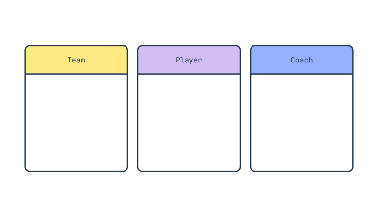
Step3: Add attributes.
Below the class name, in the middle box, is where you’d put attributes, which are the structural features and descriptions of a class.
For the Team, we’d have attributes like name, city and division.
For Player, it would be name, position, jerseyNumber.
And for Coach, we can say name, role, experience.
After each attribute goes a colon followed by the type of data. For example, “String” would be used for most text and “Integer” for numbers.
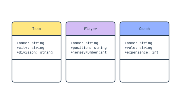
Step4: Add methods
Also referred to as functions or operations are the behavioral features of a class, or what that class does.
In other words, they define what actions or operations can be performed on objects of that class.
For our NFL example, it might look like this:
Team: playGame(), hireCoach()
Player: playGame(), train()
Coach: trainTeam(), makeStrategy()
The () represents a function that would be programmed at a later time.
Note that both attributes and methods appear in list form, with a lowercase letter and no space between words.
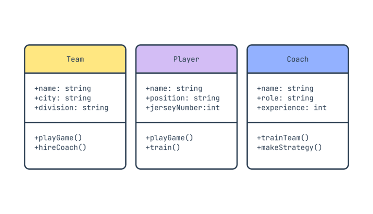
As for those symbols: +,-, # or ~, they’re the visibility of that attribute or method and its access privileges to other classes.
– = Private, meaning no accesses from other classes
+ = Public, accessible to other classes
# = Protected, accessible by the same class or subclasses
~ = Package, can be used by any class in the same package
Step5: Show relationships
Relationships can be defined in quite a few ways in class diagrams. To show the most important ones, we’ll expand our NFL example a touch throughout this section.
Inheritance
Also known as generalization, this is a relationship where a subclass inherits attributes, methods and other relationships from a superclass.
In the NFL example, if we add the classes of Quarterback, Running Back and Left Tackle, they would inherit the attributes and methods of the player class. Player would be the superclass or parent in the relationship and the position would be the child, or subclass.
If we change an attribute in the player class, all those connected to it will inherit the change. In the class diagram,
inheritance is shown with a solid line and hollow arrow.
A note about classes here, if we do add a bunch of positions, the player class turns into what’s known as an abstract class.
That’s one that serves as a blueprint for others below it and provides common structure and behavior.
The way to indicate this on our NFL diagram is either <<Player>> ;or with italics, Player.
Association
Sometimes called simple association, this is a relationship that indicates one class is related to another but not necessarily dependent.
For example, in the NFL, coaches are associated with teams, teams can have multiple coaches and other teams have coaches.
We display this with a solid line connecting the associated classes.
The relationship can also be directional, if that’s the case, you can use a filled-in arrowhead with the head ending at the smaller class.
So team would point and connect to player.

Aggregation
A special type of association, aggregation is where one class contains, or is composed of, other classes. A whole and its parts.
These parts can exist independently of the larger class and may be shared among multiple wholes.
With our football example, a team will aggregate players, but players can still exist on other teams or as free agents.
The shape of this connection is a hollow diamond attached to the “part” with a solid line going back to the “whole” or class.
Composition
On the flipside is composition, where a part cannot exist without the whole, or superclass.
Expanding the example further and adding a couple more classes; stadiums and snack bars. If the team’s stadium is torn down,
the snack bar can’t exist.
This is drawn with a solid line and filled in diamond at the superclass, or stadium in this case.
Dependency
This is a relationship where one class relies on another in some way, often through method parameters,
return types or temporary associations.
Coaches and players are related in this way, where the coach depends on the performance data or behavior of players
to make strategic decisions.
We’d show this with a dashed line and an open arrow.

Step6: Add multiplicity notation (if necessary)
Multiplicity specifies how many instances of one class are associated with instances of another class in an association.
For our NFL example, the player and team association would have multiplicity notation to indicate there are multiple players on a team.
The way we show that on the structure diagram is as follows:
– 0..1 = zero to one
– 1 = exactly one
– 0..* = zero to many
– 1..* = one to many
– n..m = specific number range
Note: a real-world class diagram for the NFL would involve way more classes and relationships to capture the full complexity of the league, including divisions, conferences, stadiums, game schedules and oh so much more.

Step7: Add multiplicity notation (if necessary)
Once you have everything in place, it’s time to do what you should do with every diagram,
map or document you put together; review it and edit as needed.
The goal is to visualize your system as clearly and cleanly as possible and now you’re equipped to create your own class diagram.
Credit : https://slickplan.com/blog/how-to-make-a-uml-diagram
